Eureka AIR delivers breakthrough ideas for toughest innovation challenges, trusted by R&D personnel around the world.

Heterogeneous proppant placement in a fracture with removable channelant fill

a proppant and fracture technology, applied in the direction of fluid removal, wellbore/well accessories, chemistry apparatus and processes, etc., can solve the problems of excessive fracture closure and difficult control of the placement of proppant-containing fluid, and achieve the effect of inhibiting the differential settling of proppan

Inactive Publication Date: 2009-09-01
SCHLUMBERGER TECH CORP
View PDF26 Cites 174 Cited by
  • Summary
  • Abstract
  • Description
  • Claims
  • Application Information

AI Technical Summary

Benefits of technology

[0014]The treatment fluid can alternatively or additionally include a mixture of proppant and channelant during the injection, and the method can include the step of segregating the proppant and channelant for the fracture placement. In an embodiment, the segregation can be facilitated by density differences between the proppant and channelant. Alternatively or additionally, the segregation can be facilitated by hydroaffinity differences between the proppant and channelant.
[0015]Channelant in one embodiment can include a solid acid-precursor to generate acid in the fracture. The generated acid can be used for gel breaking in the fracturing fluid. In another embodiment, the generated acid can etch surfaces of the formation to enlarge the channels. Alternatively or additionally, the generated acid can facilitate consolidation of the proppant clusters.
[0018]In an embodiment, the channelant can include fibers. The fibers can be, for example, glass, ceramics, carbon including carbon-based compounds, metal including metallic alloys, or the like, or a combination thereof, or a polymeric material such as PLA, PGA, PET, polyol, or the like, or a combination thereof. In an embodiment, the fibers can form of a fiber-based network. In an embodiment, the fibers can provide reinforcement and consolidation of the proppant. In another embodiment, the fibers can inhibit differential settling of proppant in the treatment fluid.

Problems solved by technology

However, the positioning of the proppant-containing fluid is difficult to control.
This underride can result in non-uniform distribution of proppant clusters, which in turn can lead to excessive fracture closure where there is not enough proppant and constricted flow channels where there is too much proppant.

Method used


Image

  • Heterogeneous proppant placement in a fracture with removable channelant fill
  • Heterogeneous proppant placement in a fracture with removable channelant fill
  • Heterogeneous proppant placement in a fracture with removable channelant fill

Examples


Embodiment Construction

[0027]At the outset, it should be noted that in the development of any such actual embodiment, numerous implementation-specific decisions must be made to achieve the developer's specific goals, such as compliance with system related and business related constraints, which will vary from one implementation to another. Moreover, it will be appreciated that such a development effort might be complex and time consuming but would nevertheless be a routine undertaking for those of ordinary skill in the art having the benefit of this disclosure.

[0028]The description and examples are presented solely for the purpose of illustrating the preferred embodiments of the invention and should not be construed as a limitation to the scope and applicability of the invention. While the compositions of the present invention are described herein as comprising certain materials, it should be understood that the composition could optionally comprise two or more chemically different materials. In addition,...


PUM


Abstract

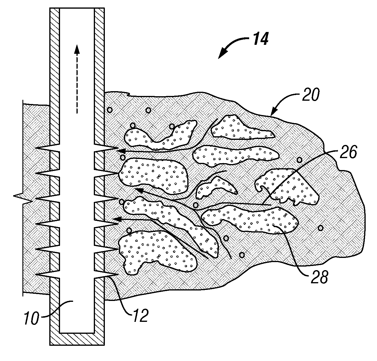
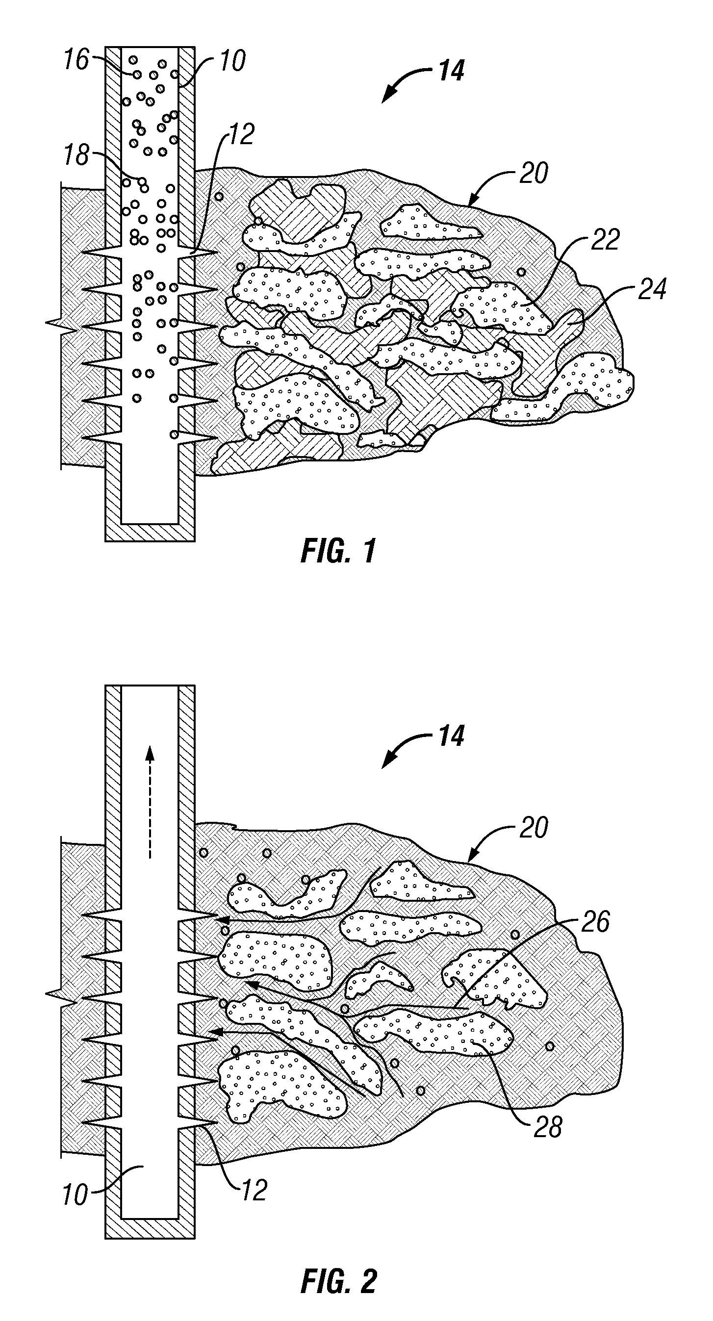
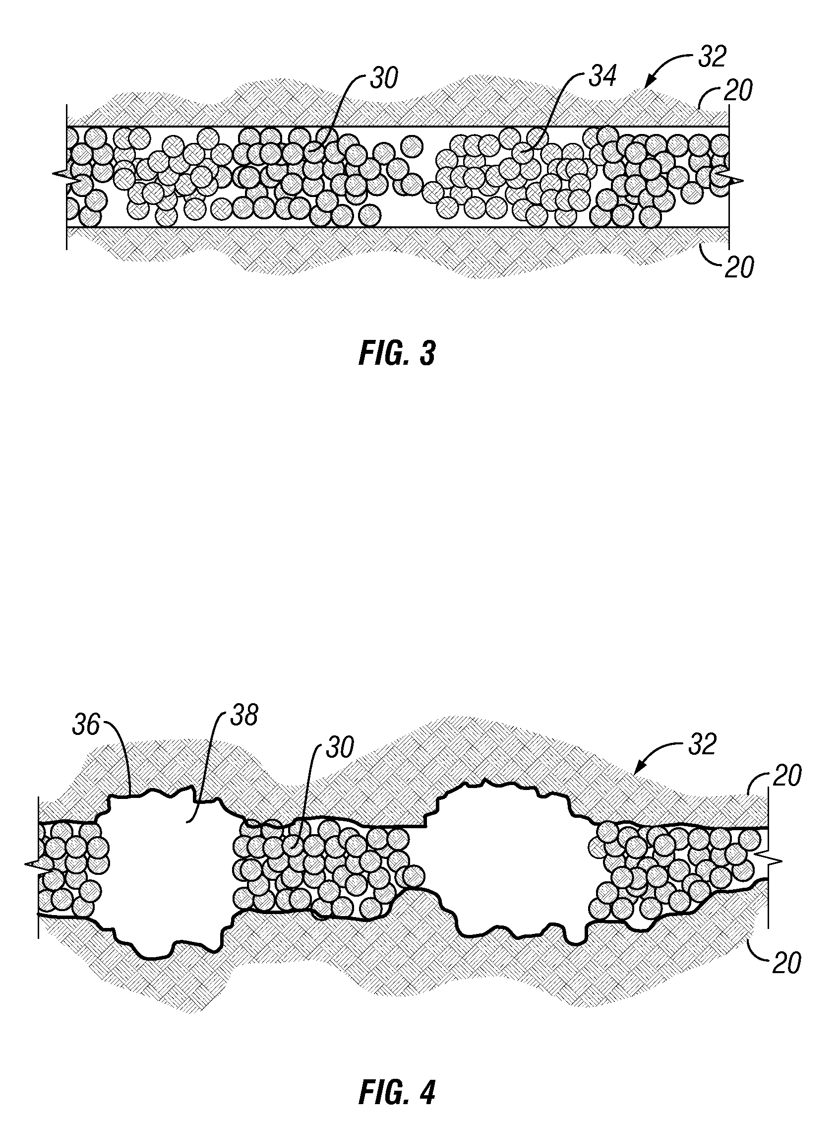
A method of heterogeneous proppant placement in a subterranean fracture is disclosed. The method comprises injecting well treatment fluid including proppant (16) and proppant-spacing filler material called a channelant (18) through a wellbore (10) into the fracture (20), heterogeneously placing the proppant in the fracture in a plurality of proppant clusters or islands (22) spaced apart by the channelant (24), and removing the channelant filler material (24) to form open channels (26) around the pillars (28) for fluid flow from the formation (14) through the fracture (20) toward the wellbore (10). The proppant and channelant can be segregated within the well treatment fluid, or segregated during placement in the fracture. The channelant can be dissolvable particles, initially acting as a filler material during placement of the proppant in the fracture, and later dissolving to leave the flow channels between the proppant pillars. The well treatment fluid can include fibers to provide reinforcement and consolidation of the proppant and, additionally or alternatively, to inhibit settling of the proppant in the treatment fluid.

Description

FIELD OF THE INVENTION[0001]The invention relates to stimulation of wells penetrating subterranean formations, and more specifically to fracture stimulation by injection of proppant into a fracture to form regions of low resistance to flow through the fracture for the production of hydrocarbons.BACKGROUND[0002]Various methods are known for fracturing a subterranean formation to enhance the production of fluids therefrom. In the typical application, a pressurized fracturing fluid hydraulically creates and propagates a fracture. The fracturing fluid carries proppant particulates into the extending fracture. When the fracturing fluid is removed, the fracture does not completely close from the loss of hydraulic pressure; instead, the fracture remains propped open by the packed proppant, allowing fluids to flow from the formation through the proppant pack to the production wellbore.[0003]The success of the fracturing treatment may depend on the ability of fluids to flow from the formatio...

Claims


Application Information

Patent Timeline
Patent Type & Authority Patents(United States)
IPC IPC(8): E21B43/267
CPCC09K8/665C09K8/68E21B43/267C09K8/80C09K8/805C09K8/72C09K8/66
Inventor LESKO, TIMOTHYBROWN, J. ERNESTWILLBERG, DEAN M.KOSAREV, IVANMEDVEDEV, ANATOLY
Owner SCHLUMBERGER TECH CORP
Why Eureka
Eureka Blog
Learn More