
Particulate flow detection microphone

a technology of particle flow and microphone, applied in the direction of electrical transducers, transducer types, piezoelectric/electrostrictive transducers, etc., can solve the problems of non-linear response, diaphragm or plate takes a finite amount of time to respond to changes in sound wave pressure, and the mass is fini

Inactive Publication Date: 2009-08-25
SCHWARTZ DAVID M
View PDF27 Cites 26 Cited by
  • Summary
  • Abstract
  • Description
  • Claims
  • Application Information

AI Technical Summary

Problems solved by technology

Current microphone technology has two fundamental and irreducible problems: (1) the diaphragm or plate that detects sound pressure waves has a finite mass; and (2) as a consequence, the diaphragm or plate takes a finite amount of time to respond to changes in sound wave pressure.
These two problems are a source of non-linear response and loss of audio information by the microphone.
These non-linearities and losses are difficult to quantify for the simple reason that the detection methods used to study these problems contain the same flawed transducers they are attempting to measure.
In fact, there are no physical transducer systems that can accomplish this; all systems with mass necessarily have some hysteresis effects.
In real-life situations, where the input sound waves are constantly changing, this problem is exacerbated.
Listeners perceive this problem as the part of the difference between recorded audio and live audio.

Method used


Image

  • Particulate flow detection microphone
  • Particulate flow detection microphone
  • Particulate flow detection microphone

Examples


Embodiment Construction

)

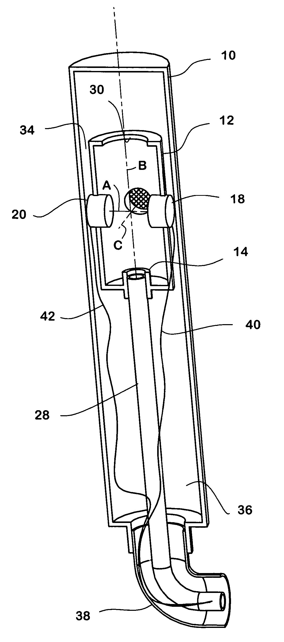
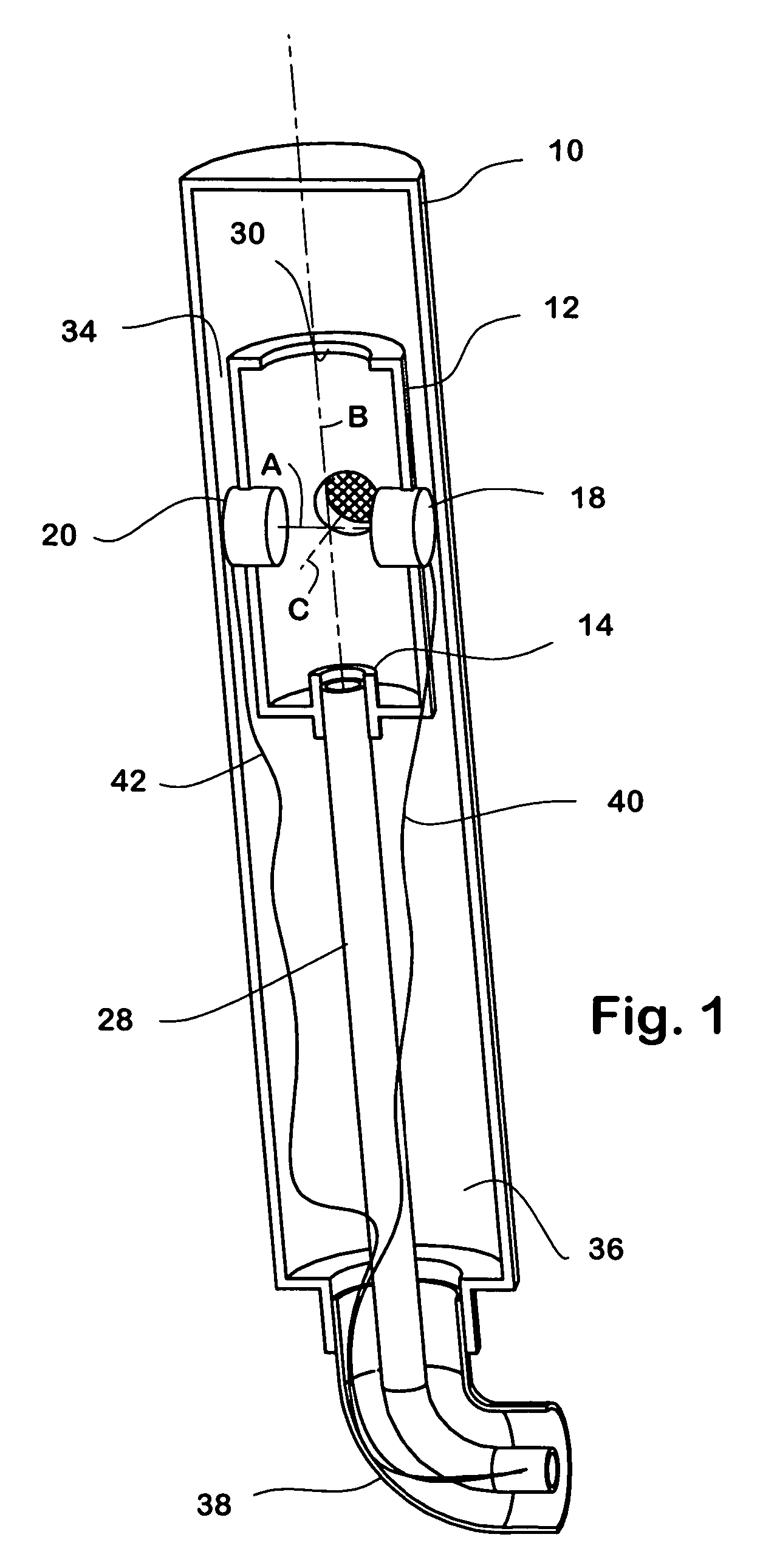
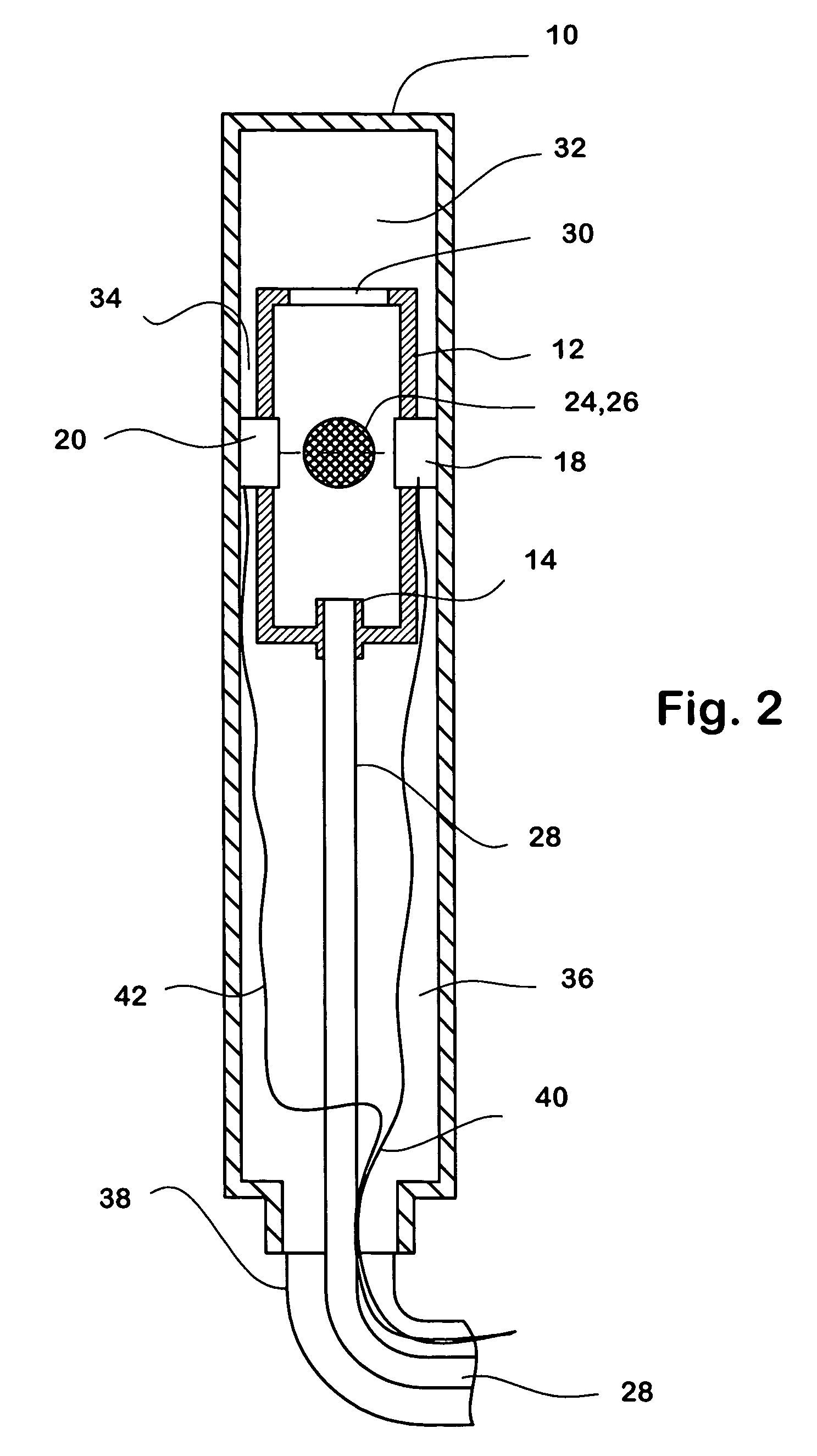
[0025]As shown in FIGS. 1 and 2, a particulate flow detection microphone includes a housing 10 containing a detection chamber 12, a particle-bearing gas nozzle 14, and a laser / photo-sensor pair 18,20. The interior surface of the detection chamber may be coated or covered with a sound-absorbing material to minimize confusing sound reflection within the chamber.

[0026]The source and detector are aligned on an axis “A” transverse to the common longitudinal axis “B” of the microphone and of the inner cylindrical detection chamber 12. The source and detector extend through the wall of the detection chamber. To admit sound to the detection chamber, the housing and the detection chamber have apertures 24,26 at locations 90° from the light source and detector; the openings are aligned on an axis “B” perpendicular to axis “A”. Both of these axes are perpendicular to the longitudinal axis “C” of the housing; thus, the axes A, B and C are orthogonal.

[0027]A small duct extends between the walls...


PUM


Abstract

Gas containing particles or droplets flowing continuously through a microphone is perturbed by sound waves. Sound-induced localized pressure changes in the gas are measured by detecting variations in gas opacity with an optical transducer disposed transverse to the flow direction.

Description

[0001]This application claims priority benefit of provisional patent application 60 / 653,133, filed Feb. 16, 2005.BACKGROUND OF THE INVENTION[0002]All modern microphones utilize a membrane or a solid plate as a diaphragm to absorb acoustical energy from sound pressure waves. That energy is then converted to electrical impulses or digital signals by a variety of means, depending on the microphone design. The impulses or signals are then stored or transmitted for immediate or later reproduction by headphones or loudspeakers.[0003]The diaphragm or flat plate introduces distortions, non-linear effects, and attenuation into the signal. This is the inevitable consequence of the physical nature of the device. While sound waves travel in only one direction from the source (reflected energy from other surfaces complicates the situation), the diaphragm or plate must travel in two directions, forward and back, in order to maintain its position in the microphone housing. This undesirable bi-dire...

Claims


Application Information

Patent Timeline
Patent Type & Authority Patents(United States)
IPC IPC(8): H04R25/00H04R11/04H04R17/02H04R19/04H04R9/08H04R21/02
CPCH04R23/008H04R2410/00
Inventor SCHWARTZ, DAVID M.
Owner SCHWARTZ DAVID M
Learn More