Eureka AIR delivers breakthrough ideas for toughest innovation challenges, trusted by R&D personnel around the world.

Interactive directed light/sound system

a directed light and sound system technology, applied in the field of interactive directed light/sound system, can solve the problems of insufficient accuracy of simple visible light image capture, difficult motion capture, complex motion capture techniques,

Inactive Publication Date: 2009-08-18
MICROSOFT TECH LICENSING LLC
View PDF56 Cites 481 Cited by
  • Summary
  • Abstract
  • Description
  • Claims
  • Application Information

AI Technical Summary

Benefits of technology

[0012]The present invention includes a system that allows easy and unencumbered real time interactions between people and reorientable directed light and / or sound systems (henceforth referred to as directed beams) using people's (or other objects') movement, position, and shape as input. The output of this system includes the real time physical reorienting of the directed beams and real time changes in the content projected by the directed beams.

Problems solved by technology

Although motion capture provides benefits and advantages, motion capture techniques tend to be complex.
Techniques that rely on simple visible-light image capture are usually not accurate enough to provide well-defined and precise motion capture.
Many real-world applications must work in environments where there are complex and changing background and foreground objects, changing lighting conditions and other factors that can make motion capture difficult.
However, these solutions generally require the person being tracked to wear some type of transmitting device.

Method used


Image

  • Interactive directed light/sound system
  • Interactive directed light/sound system
  • Interactive directed light/sound system

Examples


Embodiment Construction

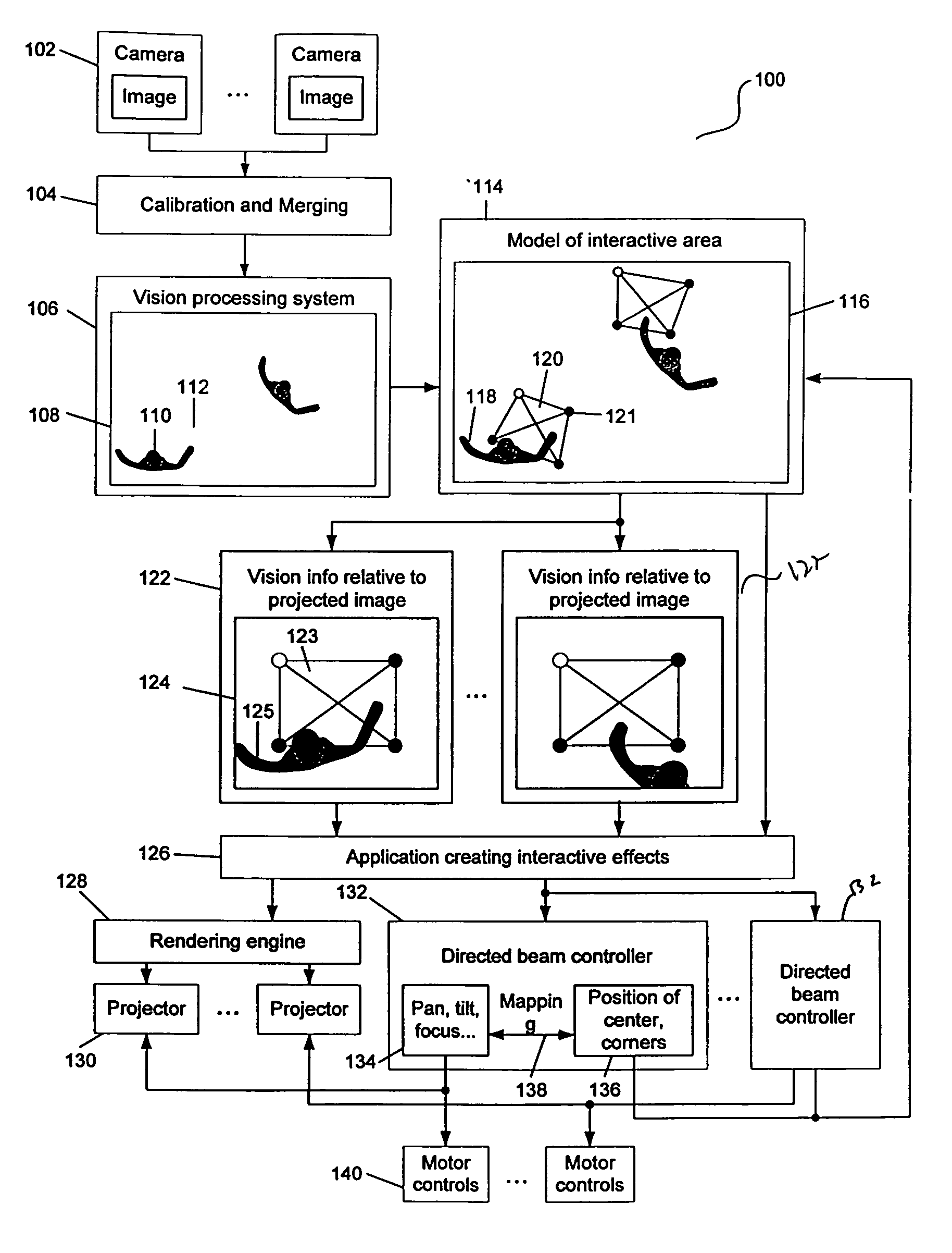
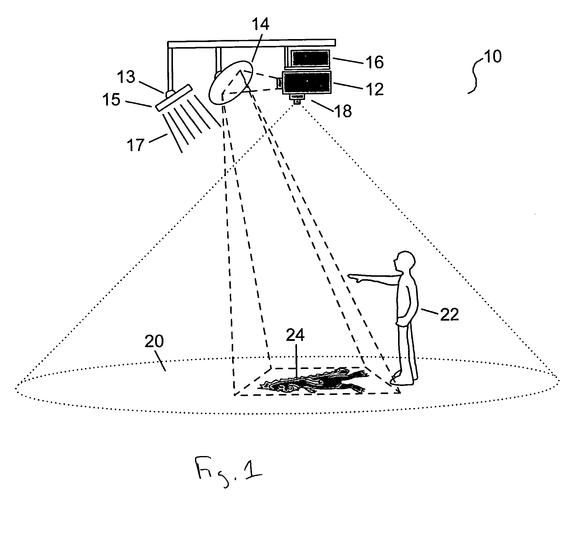
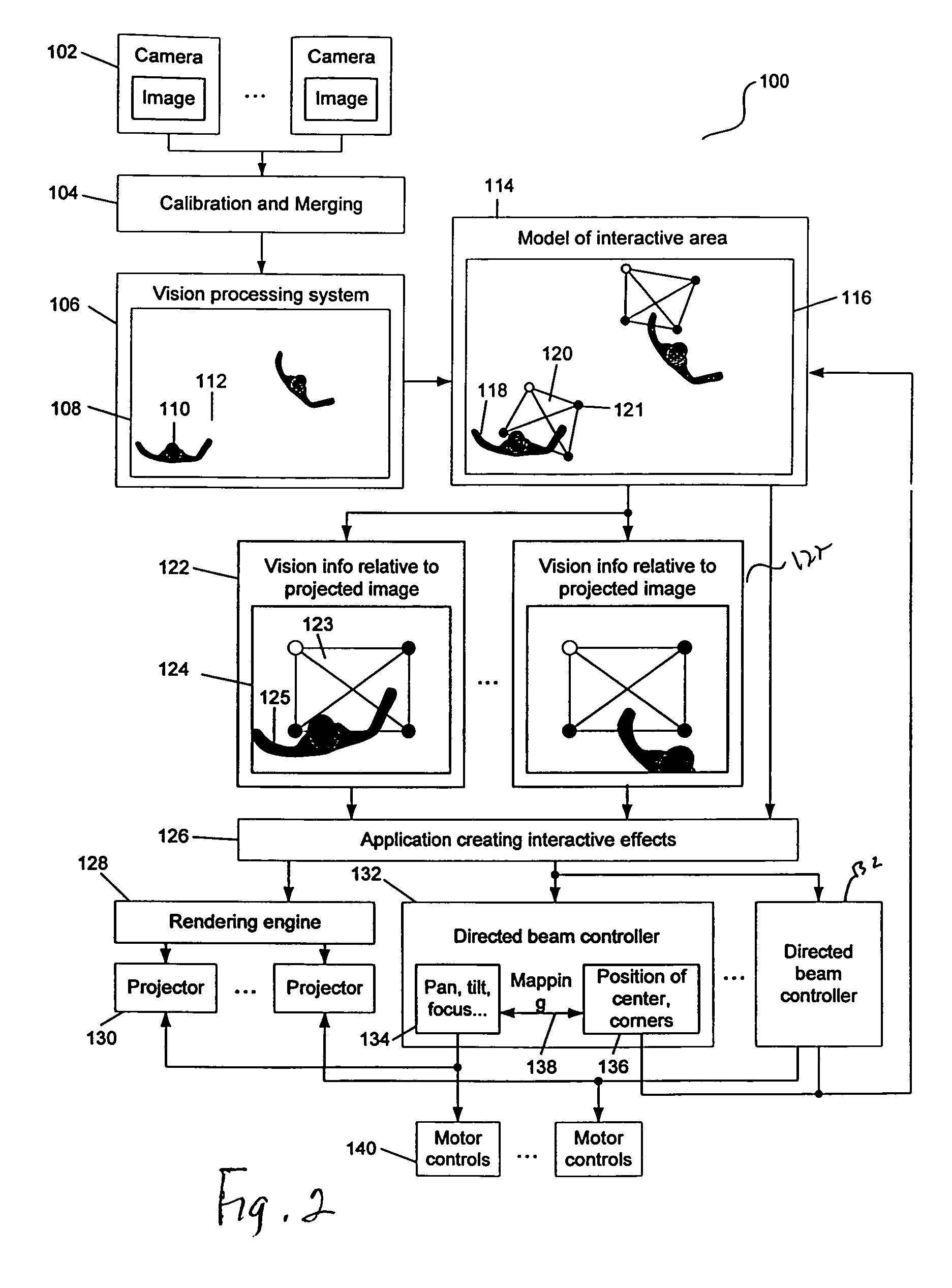
[0025]The present invention in the form of one or more exemplary embodiments will now be described. FIG. 1 illustrates one exemplary embodiment of the present invention. This exemplary embodiment includes a system 10 having the following components: a co-located video projector 12, a mirror 14, a computer 16 and an image detection system, such as, a camera 18, mounted on a ceiling.

[0026]The camera 18 is configured to view and capture information in an interactive area 20. For example, as shown in FIG. 1, the camera 18 is able to capture information relating to a person or user 22 located within the interactive area 20. The captured information may take various forms, and may include audio data as well as image data. The captured information is based on actions taken by the person 22 within the interactive area 20. Such actions include, for example, natural movements of the person 22 and interactions between the person 22 and the projected image 24. It should be noted information rel...


PUM


Abstract

An interactive directed beam system is provided. In one implementation, the system includes a projector, a computer and a camera. The camera is configured to view and capture information in an interactive area. The captured information may take various forms, such as, an image and / or audio data. The captured information is based on actions taken by an object, such as, a person within the interactive area. Such actions include, for example, natural movements of the person and interactions between the person and an image projected by the projector. The captured information from the camera is then sent to the computer for processing. The computer performs one or more processes to extract certain information, such as, the relative location of the person within the interactive area for use in controlling the projector. Based on the results generated by the processes, the computer directs the projector to adjust the projected image accordingly. The projected image can move anywhere within the confines of the interactive area.

Description

CROSS-REFERENCES TO RELATED APPLICATION(S)[0001]The present application claims the benefit of priority under 35 U.S.C. § 119 from U.S. Provisional Patent Application Ser. No. 60 / 433,158, entitled “INTERACTIVE DIRECTED LIGHT / SOUND SYSTEM” filed on Dec. 13, 2002, the disclosure of which is hereby incorporated by reference in its entirety for all purposes.[0002]The present application is also related to U.S. patent application Ser. No. 10 / 160,217, entitled “INTERACTIVE VIDEO DISPLAY SYSTEM” filed on May 28, 2002; and U.S. Patent Application Ser. No. 60 / 504,375, entitled “SELF-CONTAINED INTERACTIVE VIDEO DISPLAY SYSTEM” filed on Sep. 18, 2003, the disclosures of which are hereby incorporated by reference in its entirety for all purposes.BACKGROUND OF THE INVENTION[0003]The present invention is generally related to using human position and movement, as well as other visual cues, as input to an interactive system that reorients one or more directed light or sound sources and modifies thei...

Claims


Application Information

Patent Timeline
Patent Type & Authority Patents(United States)
IPC IPC(8): G06F3/033G06F3/00G06F3/01G06F3/042H04N7/18
CPCG06F3/011H04N7/183G06F3/0425H05B47/125H05B47/155Y02B20/40
Inventor BELL, MATTHEW
Owner MICROSOFT TECH LICENSING LLC
Why Eureka
Eureka Blog
Learn More