
Display apparatus and method of driving the same

a technology of display apparatus and drive mechanism, which is applied in the direction of identification means, instruments, static indicating devices, etc., can solve the problems of deteriorating image quality, inability to achieve satisfactory pre-charge effect in this technology, etc., and achieve the reduction of storage capacity required for storing the specified pre-charge voltage, and the time required to specify the optimal pre-charge voltage.

Inactive Publication Date: 2009-08-18
ELEMENT CAPITAL COMMERCIAL CO PTE LTD
View PDF23 Cites 128 Cited by
  • Summary
  • Abstract
  • Description
  • Claims
  • Application Information

AI Technical Summary

Benefits of technology

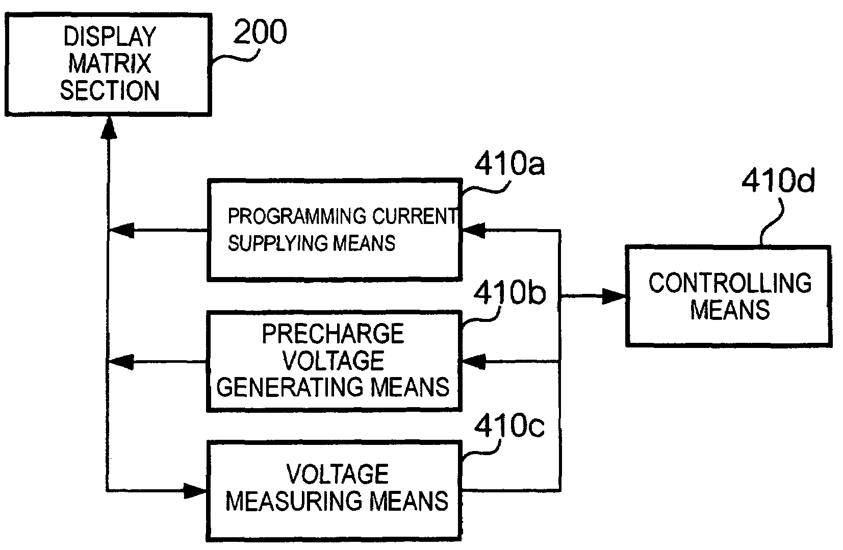
"The present invention provides a technology for preventing non-uniform precharging in a display apparatus that includes current drive type pixels. Non-uniform precharging can cause non-uniform light emission and deterioration of the quality of a displayed image. The technology provides a solution by specifying precharge voltages as voltages to be applied to data lines before the internal state of pixels is set, in accordance with voltages appearing in the data lines after supplying a predetermined current. This ensures a uniform precharging effect even if the threshold voltage of the driving transistor in a pixel is not uniform. The precharge voltage is specified by a measuring means that measures the voltages in the data lines after supplying the predetermined current. The supplying means supplies the predetermined current to all pixels in the display region."

Problems solved by technology

Accordingly, a satisfactory effect by the precharging cannot be obtained in this technology disclosed in Patent document 1.
In other words, the quality of a displayed image may deteriorate.

Method used


Image

  • Display apparatus and method of driving the same
  • Display apparatus and method of driving the same
  • Display apparatus and method of driving the same

Examples


Embodiment Construction

[0053]Hereinafter, preferred embodiments of the present invention will be described in detail with reference to the accompanying drawings.

[A. Structure]

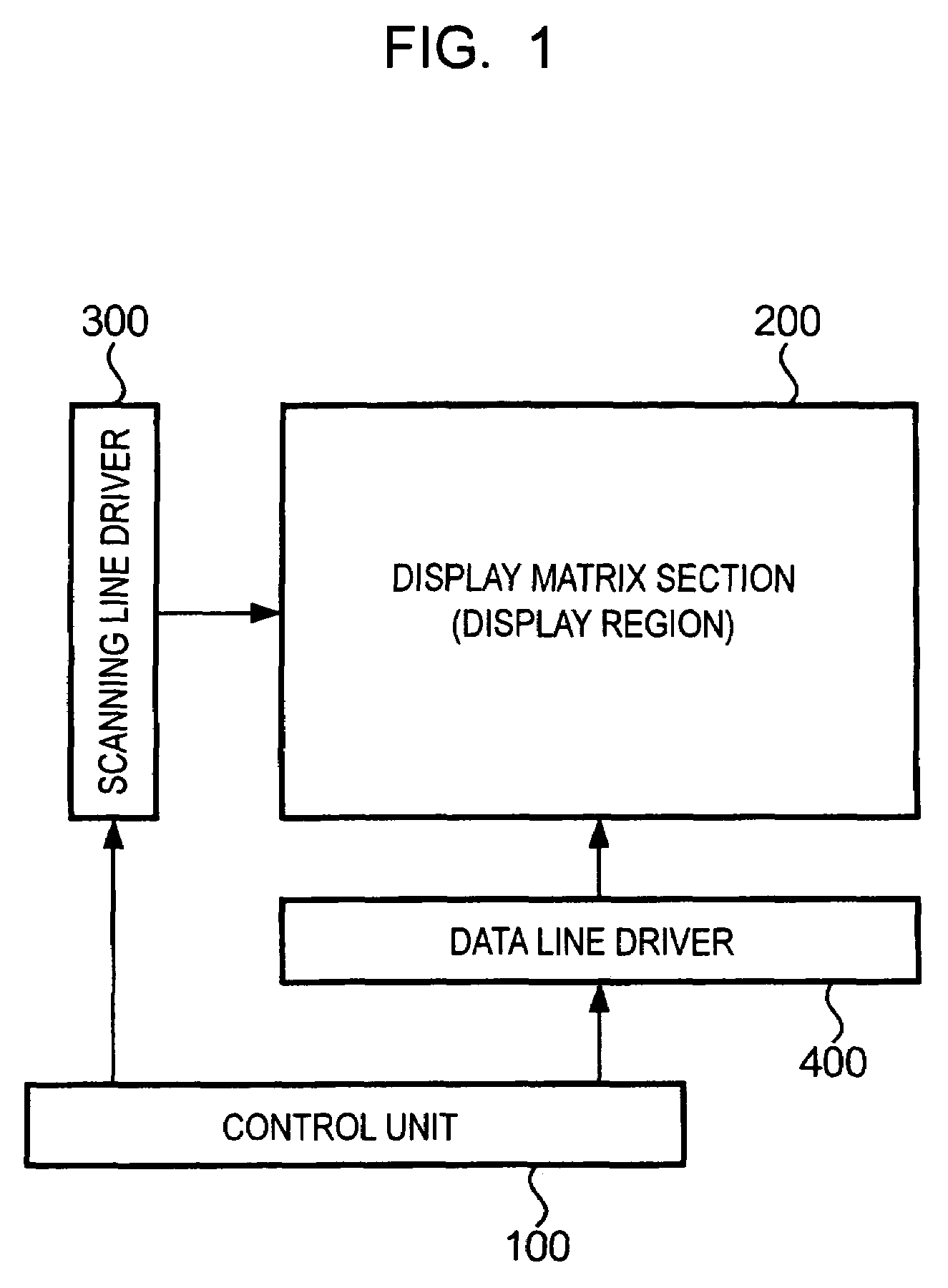
[0054]FIG. 1 is a schematic block diagram of a display apparatus according to an embodiment of the present invention. As shown in FIG. 1, the display apparatus includes a control unit 100, a display matrix section 200, a scanning line driver 300, and a data line driver 400. The control unit 100 generates scanning line driving signals and data line driving signals, which are used to perform a display on the display matrix section 200, and supplies the generated signals to the scanning line driver 300 and the data line driver 400, respectively.

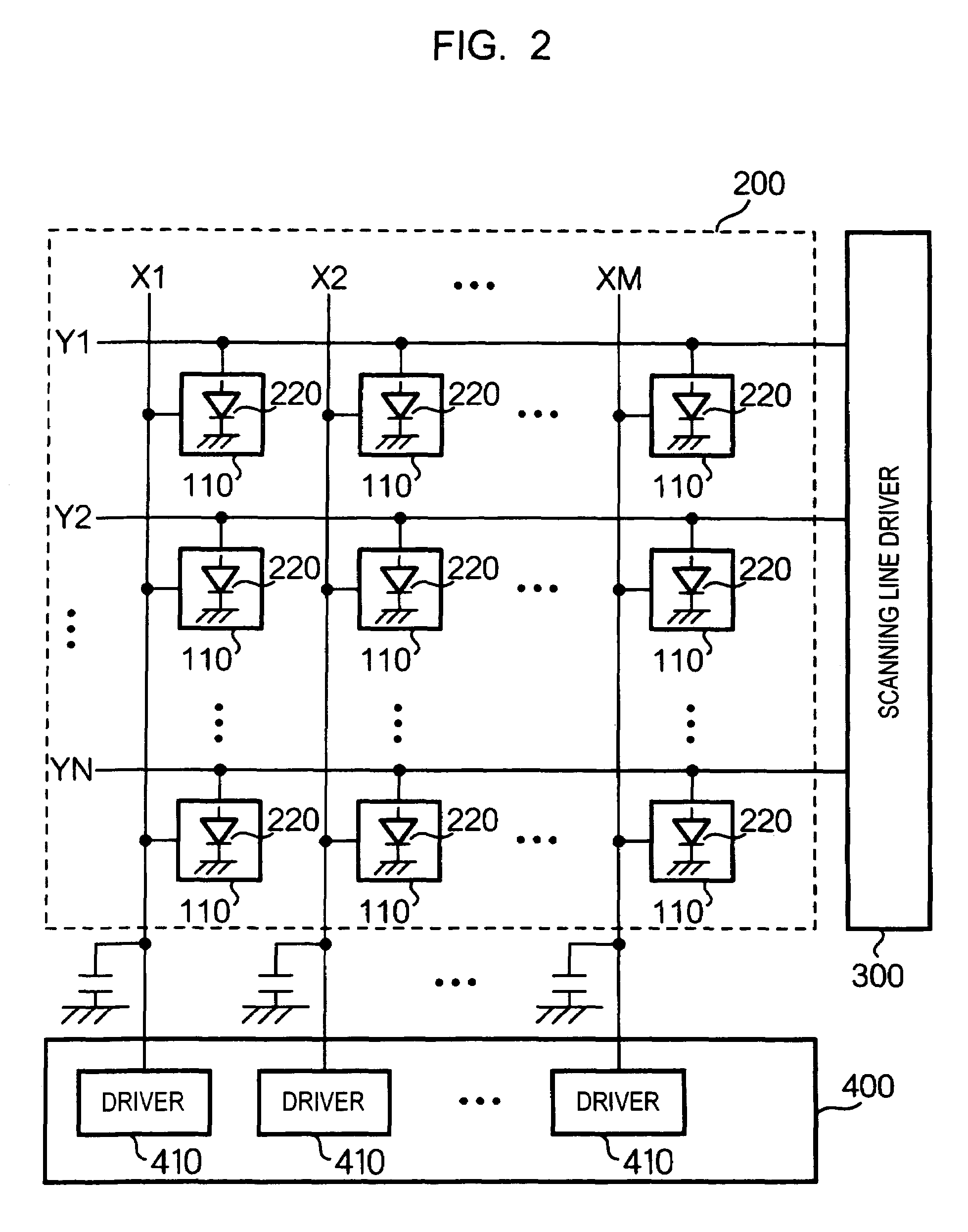
[0055]FIG. 2 is a block diagram illustrating the internal structure of the display matrix section 200 and the internal structure of the data line driver 400. As shown in FIG. 2, the display matrix section 200 includes a plurality of pixel circuits 110 arranged in a matrix (refer to FIG. 14). Each...


PUM


Abstract

To provide a technology for preventing effect of precharging from becoming nonuniform when the threshold voltage of a driving transistor included in a current drive type pixel circuit is nonuniform. In the technology, before setting the internal state of each of current drive type pixel circuits, provided to corresponded to intersections of a plurality of data lines and a plurality of scanning lines, in accordance with light emission grayscales, precharge voltages as voltages to be applied to the data lines are specified. A predetermined current is supplied to the current drive type pixel circuits via the data lines. A precharge voltage is specified in accordance with voltages appearing in the data lines after the predetermined current is supplied.

Description

BACKGROUND OF THE INVENTION[0001]1. Field of Invention[0002]The present invention relates to technology of setting the internal state of a current drive type pixel circuit corresponding to light emission grayscales for the current drive type pixel circuit at a high speed.[0003]2. Description of Related Art[0004]In recent years, an electro-optical apparatus using an organic electroluminescent (EL) element has been progressively developed. The organic EL element is a self-luminous element and does not require a backlight. Accordingly, a display apparatus using the organic EL element is expected to achieve low power consumption, a wide viewing angle, and a high contrast ratio. In this specification, the term “electro-optical apparatus” means an apparatus that converts electrical signals into light. The electro-optical apparatus normally converts electrical signals representing an image into light representing the image and is particularly suitable to implementation of a display apparat...

Claims


Application Information

Patent Timeline
Patent Type & Authority Patents(United States)
IPC IPC(8): G09G3/30H01L51/50G09F9/30G09G3/00G09G3/20G09G3/36H05B33/00H05B33/14
CPCG09G3/325G09G3/3283G09G2300/0842G09G2300/0852G09G2300/0861G09G2320/0693G09G2320/0285G09G2320/029G09G2320/0295G09G2320/041G09G2320/043G09G2310/0248G09G3/30
Inventor MIYAZAWA, TAKAO
Owner ELEMENT CAPITAL COMMERCIAL CO PTE LTD
Learn More