
Flagpole top support bracket assembly

a top support bracket and flagpole technology, applied in the field of flagpole hardware, can solve the problems of hardware not being able to be immovably mounted on the sections, unnecessarily complicating the replacement of the bracket, and not always adequately addressed by the hardware employed

Inactive Publication Date: 2009-08-18
WIESE MICHAEL J
View PDF66 Cites 14 Cited by
  • Summary
  • Abstract
  • Description
  • Claims
  • Application Information

AI Technical Summary

Benefits of technology

[0012]One significant advantage of the present invention is the ability to remove the support of the assembly from the cap (and replace the support on the cap) without having to remove the cap (or any ornament mounted on the cap) from the flagpole. Another advantage is the protection of the flagpole from wear due to the rotation of the support.

Problems solved by technology

Due to their telescopic nature, these flagpoles present challenges that are not always adequately addressed by the hardware employed on the conventional fixed length flagpoles.
For example, because the sections telescope in and out of each other, the hardware cannot be immovably mounted on the sections, and must be able to be removed or at least slide along the length of the sections.
It is believed that this requirement unnecessarily complicates the replacement of the bracket, and increases the risk that the bracket will be incorrectly removed or replaced, or that the ornament will become damaged in the time period that it is removed from the pole.
Furthermore, in at least some of the known designs, improper tightening of the ornament or other retaining structure will restrict or prevent rotation of the bracket, or may allow too much movement of the bracket relative to the pole, which can lead to excessive wear and premature failure.
Other designs employ inserts that insert into the top end of the pole to hold the bracket in place, but again improper positioning of the insert can resist rotation.
Further, the known insert design requires the bracket to contact and ride on the upper edge of the hollow flag pole, and thus could also lead to excessive wear and premature failure if the top edge is not sufficiently smooth or the materials used for the flagpole and the bracket are not of similar wear resistance.

Method used


Image

  • Flagpole top support bracket assembly
  • Flagpole top support bracket assembly
  • Flagpole top support bracket assembly

Examples


Embodiment Construction

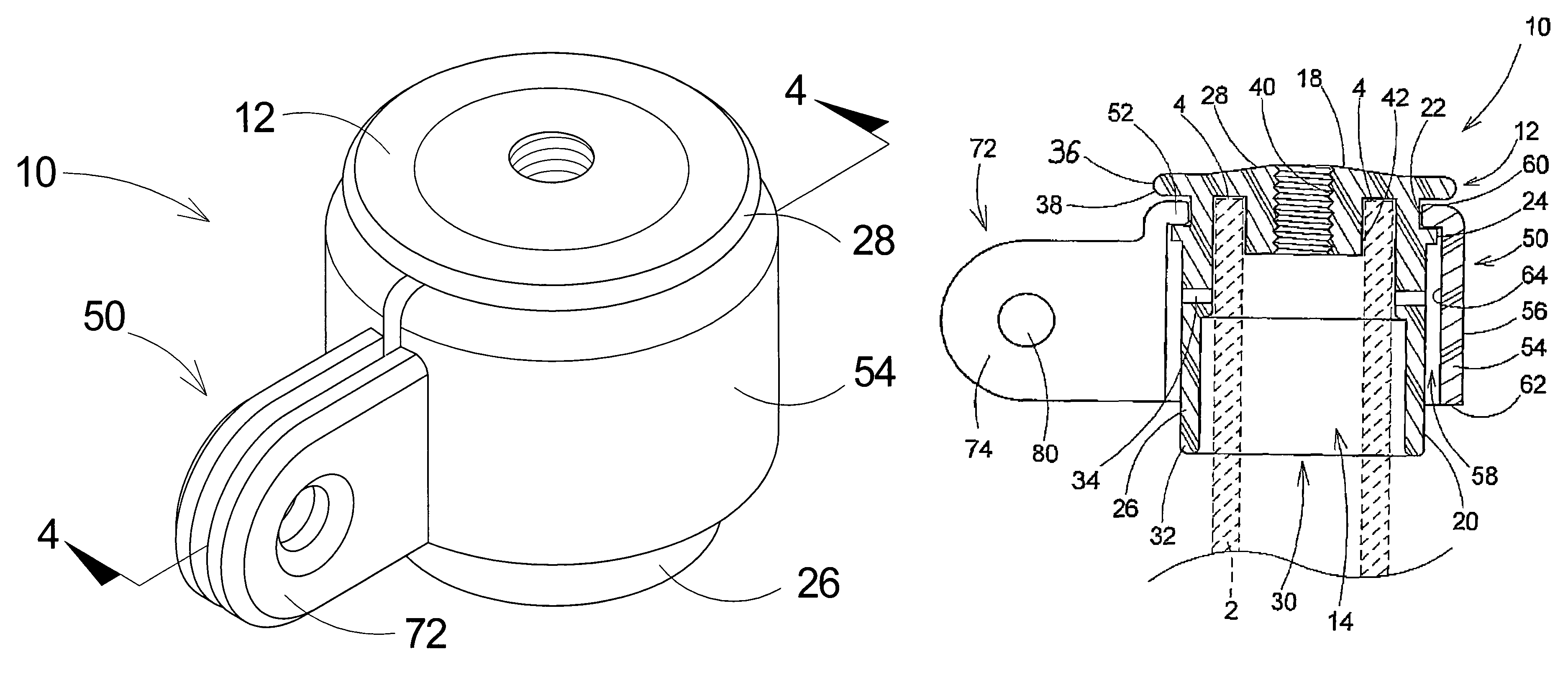
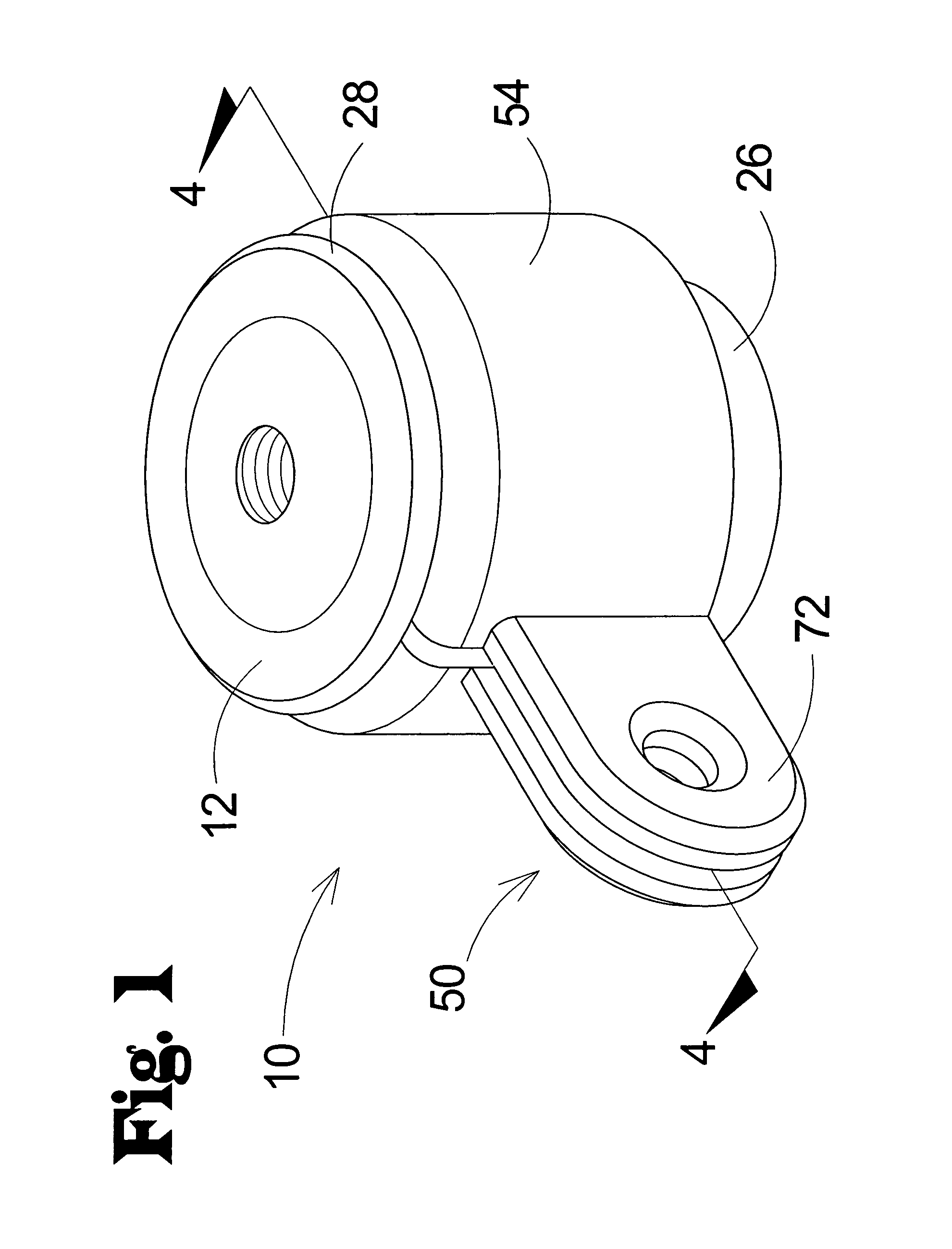
[0020]With reference now to the drawings, and in particular to FIGS. 1 through 5 thereof, a new flagpole top support bracket assembly embodying the principles and concepts of the present invention and generally designated by the reference numeral 10 will be described.

[0021]As best illustrated in FIGS. 1 through 6, the flagpole top support bracket assembly 10 generally comprises a cap 12 and a support 50 mounted on the cap.

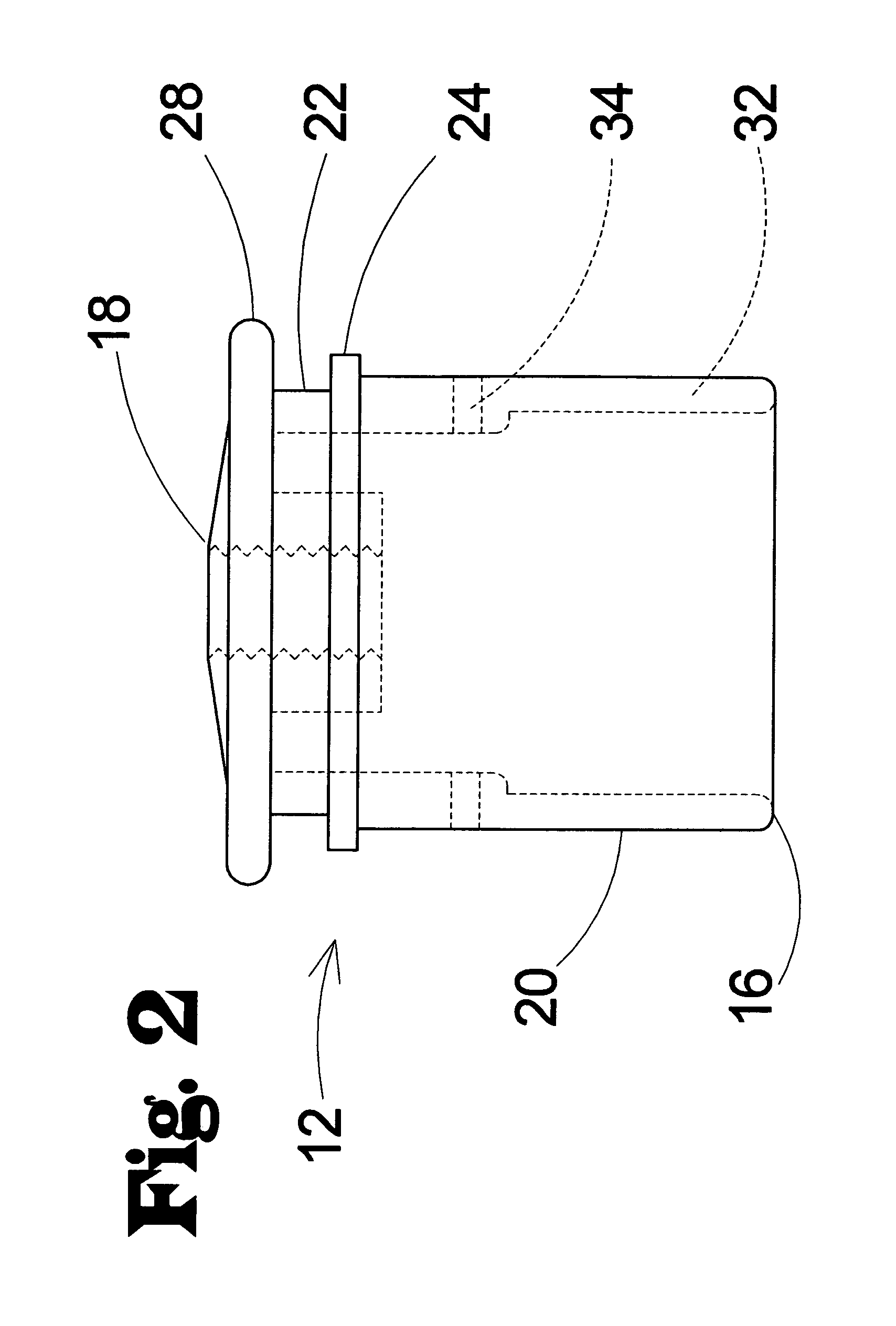
[0022]The flag support bracket assembly 10 of the invention is for use on a flagpole 2, and is suitably positionable on the top end 4 of the flagpole 2. The support bracket assembly 10 may comprise a cap 12 for mounting on the top end 4 of the flagpole 2. The cap 12 may define a cavity 14 for receiving an upper portion of the flagpole 2. The cavity 14 may extend inwardly from a lower end 16 of the cap 12. The cap 12 also has an upper end 18 that is located opposite of the lower end 16, and the cap 12 has an outer surface 20.

[0023]In one significant aspect of the in...


PUM


Abstract

A flagpole top support bracket assembly for a top end of a flagpole is disclosed, and includes a cap for mounting on the upper end of the flagpole. The cap defines a cavity for receiving an upper portion of the flagpole, and the cavity extends inwardly from an opening in a lower end of the cap. The cap has an outer surface and an annular groove formed in the outer surface. The bracket assembly further includes a support mounted on the cap, and the support is rotatable with respect to the cap. The support includes a mounting lip for resisting sliding of the support off of the cap, and the mounting lip extends inwardly toward the cap and is configured to be at least partially positioned in the annular groove of the cap.

Description

BACKGROUND OF THE INVENTION[0001]1. Field of the Invention[0002]The present invention relates to flagpole hardware and more particularly pertains to a new flagpole top support bracket assembly for mounting on the top of a flagpole to support a flag.[0003]2. Description of the Prior Art[0004]Flagpoles, and the various types of hardware used in association with the flagpoles, are generally well known. The most common and recognized flagpole are those that have a fixed length and employ some type of rope or cable to support and move the flag up and down the pole as needed. Less common are telescopic flagpoles, such as is described in my U.S. Pat. No. 6,951,185, issued Oct. 4, 2005 and incorporated here by reference in its entirety, which are extendable and retractable. Due to their telescopic nature, these flagpoles present challenges that are not always adequately addressed by the hardware employed on the conventional fixed length flagpoles. For example, because the sections telescope...

Claims


Application Information

Patent Timeline
Patent Type & Authority Patents(United States)
IPC IPC(8): A47G29/00
CPCG09F17/00E04H12/32
Inventor WIESE, MICHAEL J.
Owner WIESE MICHAEL J
Learn More