
Protractor for calculating miter and bevel angles for installing molding

a technology bracket, which is applied in the direction of instruments, writing aids, and mechanical means, etc., can solve the problems of unintuitive combination of miter and bevel angle, complex, and inability to achieve 45° cut,

Inactive Publication Date: 2009-08-18
SANDEN CORP
View PDF20 Cites 17 Cited by
  • Summary
  • Abstract
  • Description
  • Claims
  • Application Information

AI Technical Summary

Benefits of technology

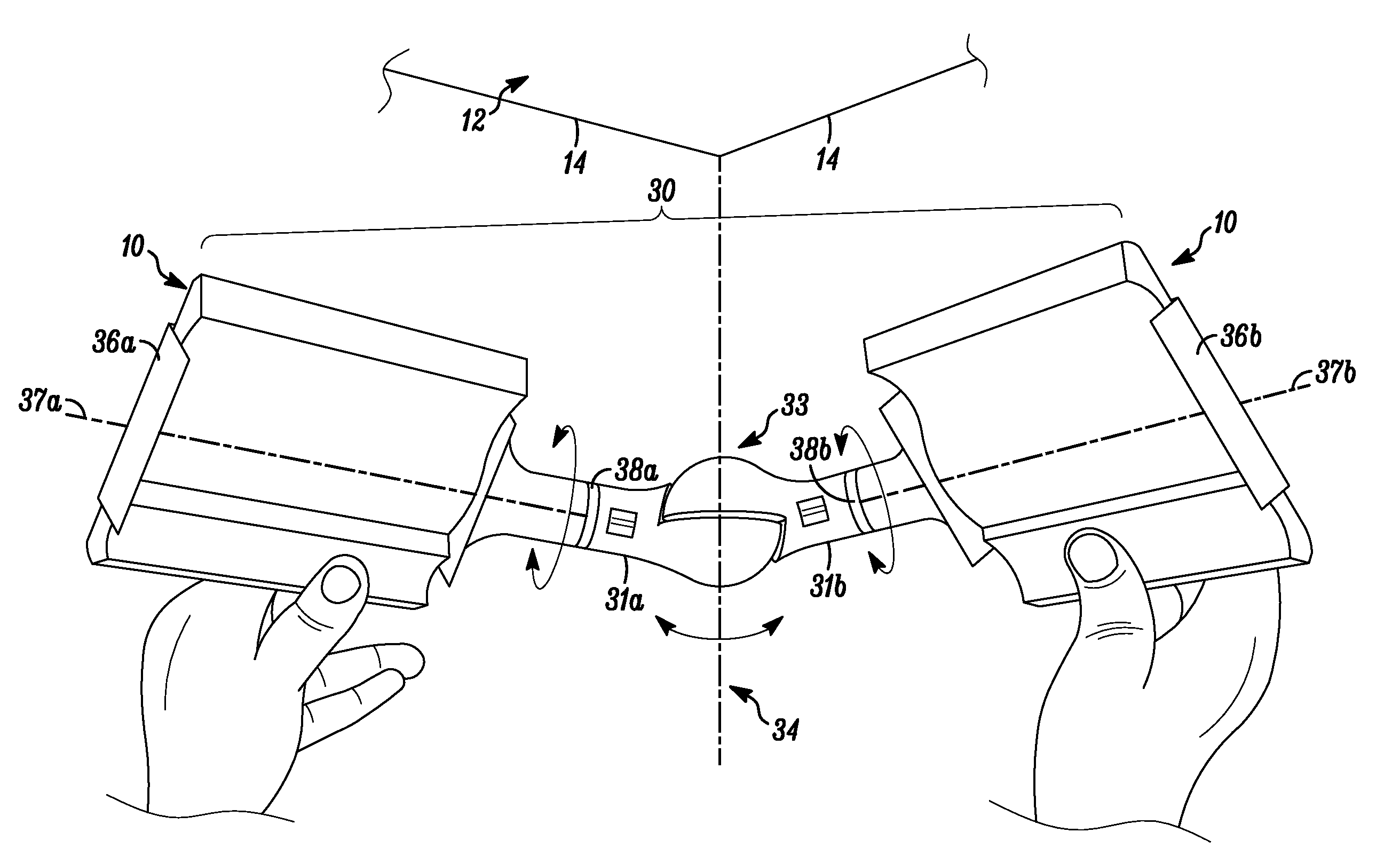
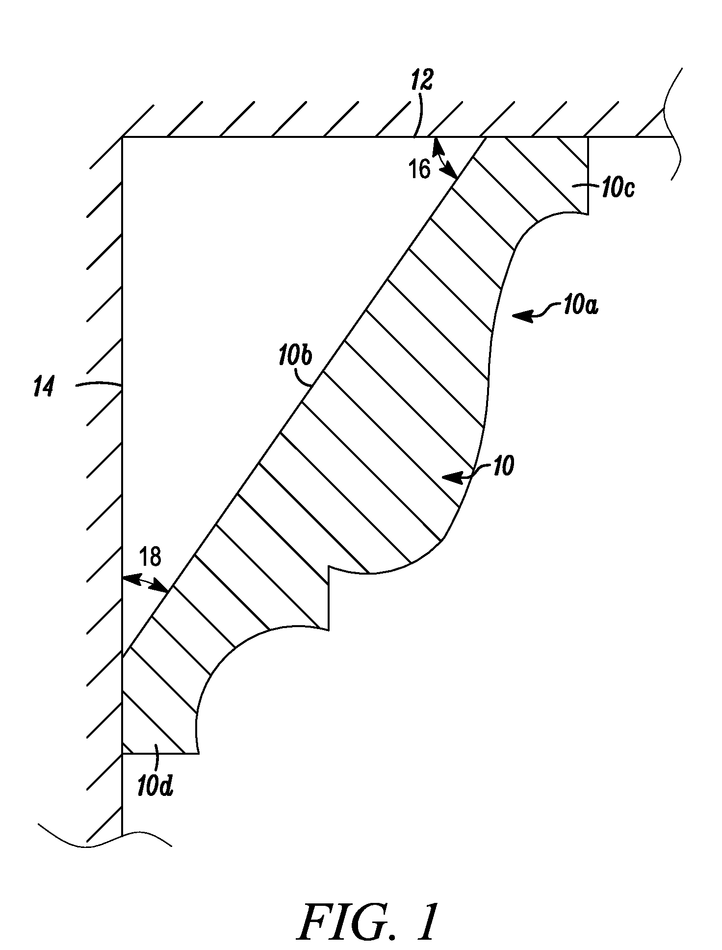
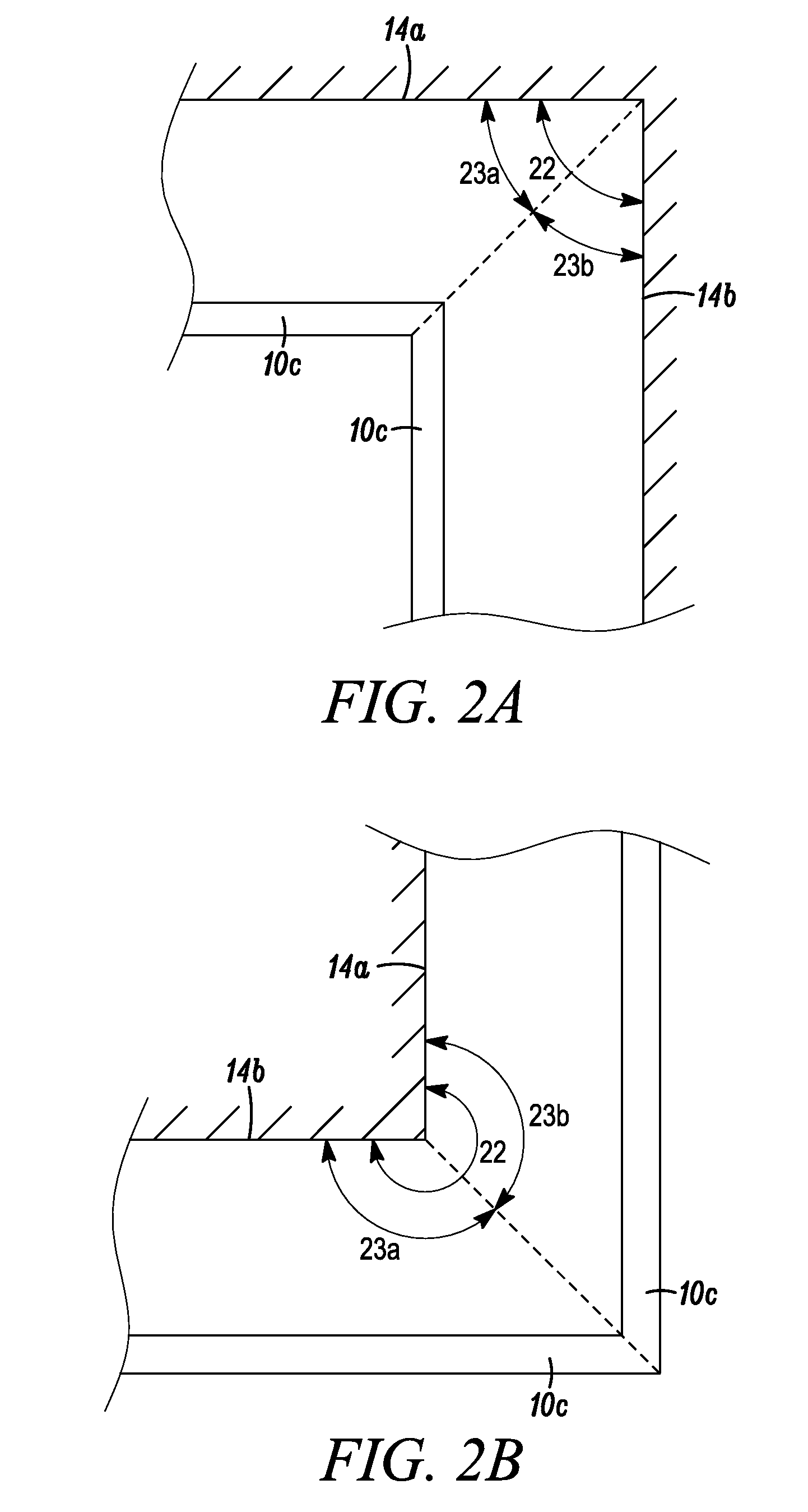
[0016]The protractor taught herein is particularly useful for the installation of crown molding and similar trim molding not residing in the same plane as the surface, or surfaces, to which it is attached when the molding or trim is to be cut laying flat on the bed of a miter saw or the like. For example, when fitted to an upper corner of a room, where two adjacent walls and the ceiling converge, the present protractor provides a digital readout of the proper bevel and miter angle settings for a miter saw so that the crown molding may be cut while laying flat on the table of the miter saw.

Problems solved by technology

The major problem with cutting trim arises from the fact that trim is usually cut lying flat on its back rather than at the installation orientation where it meets the wall, floor or ceiling.
This change in orientation means that a 45° cut can no longer be achieved by simply setting a miter saw for a 45° miter or 45° bevel angle.
A complex, unintuitive combination of miter and bevel angles is needed to achieve what otherwise would be a simple task.
This calculation is a challenge to even an experienced craftsman who will often resort to trial and error.

Method used


Image

  • Protractor for calculating miter and bevel angles for installing molding
  • Protractor for calculating miter and bevel angles for installing molding
  • Protractor for calculating miter and bevel angles for installing molding

Examples


Embodiment Construction

[0025]While this invention is susceptible of embodiment in many different forms, there is shown in the drawings and will herein be described in detail specific embodiments, with the understanding that the present disclosure of such embodiments is to be considered as an example of the principles and not intended to limit the invention to the specific embodiments shown and described. In the description below, like reference numerals are used to describe the same, similar or corresponding parts in the several views of the drawings. This detailed description defines the meaning of the terms used herein and specifically describes embodiments in order for those skilled in the art to practice the invention.

[0026]The terms “a” or “an”, as used herein, are defined as one or as more than one. The term “plurality”, as used herein, is defined as two or as more than two. The term “another”, as used herein, is defined as at least a second or more. The terms “including” and / or “having”, as used he...


PUM


Abstract

Taught herein is a protractor capable of measuring angles within a room and angles related to the intended orientation of molding with respect to the room. Using these angles, the present invention will calculate and display the appropriate angles at which a miter saw must be set to produce mitered joints for the installation of trim and crown molding.

Description

COPYRIGHT NOTICE[0001]A portion of the disclosure of this patent contains material that is subject to copyright protection. The copyright owner has no objection to the reproduction by anyone of the patent document or the patent disclosure as it appears in the Patent and Trademark Office patent files or records, but otherwise reserves all copyright rights whatsoever.BACKGROUND OF THE INVENTION[0002]1. Field of the Invention[0003]The present invention is directed to an instrument capable of measuring angles between walls, floors, and ceilings within a room and measuring the spring angle and calculating and displaying the appropriate angles for cutting miter joints for the installation of trim and crown molding.[0004]2. Description of Related Art[0005]Throughout the history of architecture, molding has been used as a decorative embellishment and a means to cover imperfections in construction. In the present day, it is used in some form in most buildings ranging from massive edifices to...

Claims


Application Information

Patent Timeline
Patent Type & Authority Patents(United States)
IPC IPC(8): B43L7/10G01B3/56
CPCG01B3/563E04F21/0069
Inventor BOUTAN, CHRISTIAN R.
Owner SANDEN CORP
Learn More