
Generator utilizing fluid-induced oscillations

a technology of fluid-induced oscillation and generator, which is applied in the direction of wind energy generation, electric generator control, machines/engines, etc., can solve the problems of low efficiency at all but a narrow range of wind speeds, lack of cost effectiveness at lower power output levels (1 kw), and high initial capital costs

Inactive Publication Date: 2009-08-11
HUMDINGER WIND ENERGY
View PDF26 Cites 59 Cited by
  • Summary
  • Abstract
  • Description
  • Claims
  • Application Information

AI Technical Summary

Benefits of technology

"The patent describes a new generator design that effectively promotes the oscillations induced by flowing fluids, such as wind or water, to produce electricity or other types of energy. The generator includes a flexible membrane that vibrates when subject to fluid flows, and a magnetic field generator that moves with the membrane. The membrane can be attached to a supporting structure or a mass to promote vibrations. The generator can also include multiple membranes, an adjustable tension provider, and a power conditioning circuit. The technical effects of this design include improved efficiency, cost-effectiveness, and the ability to generate energy at lower speeds."

Problems solved by technology

While these turbine-based wind generators are generally useful in certain open spaces with consistently high-speed winds, drawbacks still exist, such as heavy initial capital costs, low efficiency at all but a narrow range of wind speeds, the lack of cost effectiveness at lower power outputs levels (<1 kW), etc.
However, these proposals were not satisfactory due to design complexities, added cost, the need for a complex mounting structure, low efficiency in energy production, insufficient power generation, inefficient production of vibrations, restriction to high flow speeds, etc.

Method used


Image

  • Generator utilizing fluid-induced oscillations
  • Generator utilizing fluid-induced oscillations
  • Generator utilizing fluid-induced oscillations

Examples


Embodiment Construction

[0019]In the following description, for the purposes of explanation, numerous specific details are set forth in order to provide a thorough understanding of the present disclosure. It will be apparent, however, to one skilled in the art that the present disclosure may be practiced without these specific details. In other instances, well-known structures and devices are shown in block diagram form in order to avoid unnecessarily obscuring the present disclosure.

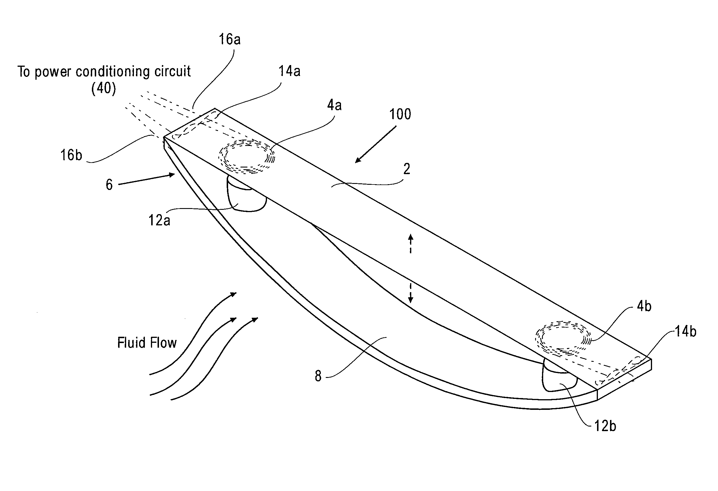
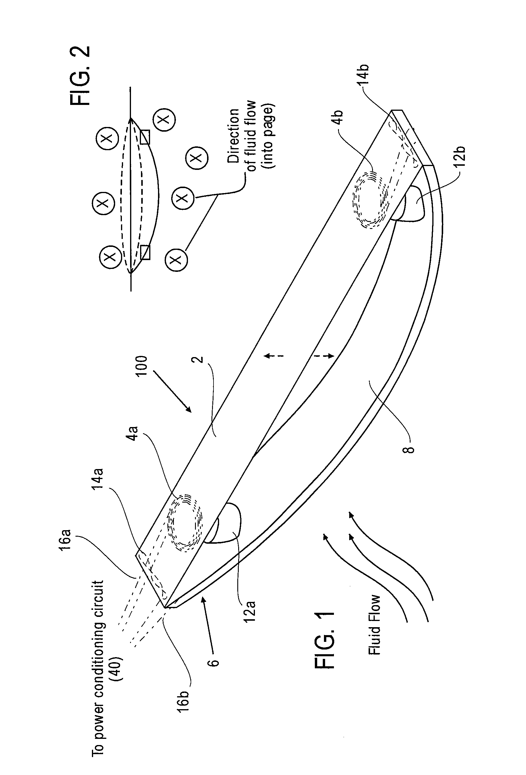
[0020]An exemplary electrical generator includes a magnetic field generator and a flexible membrane for converting energy present in fluid flows, such as air flows, water flows, tides, etc., into vibrations or oscillations. The flexible membrane includes at least one electrical conductor attached thereto and has at least two fixed ends. The membrane vibrates when subject to a fluid flow. As used herein, the term “flexible” refers to a membrane that has the ability to morph into a large variety of determinate and indeterminate ...


PUM


Abstract

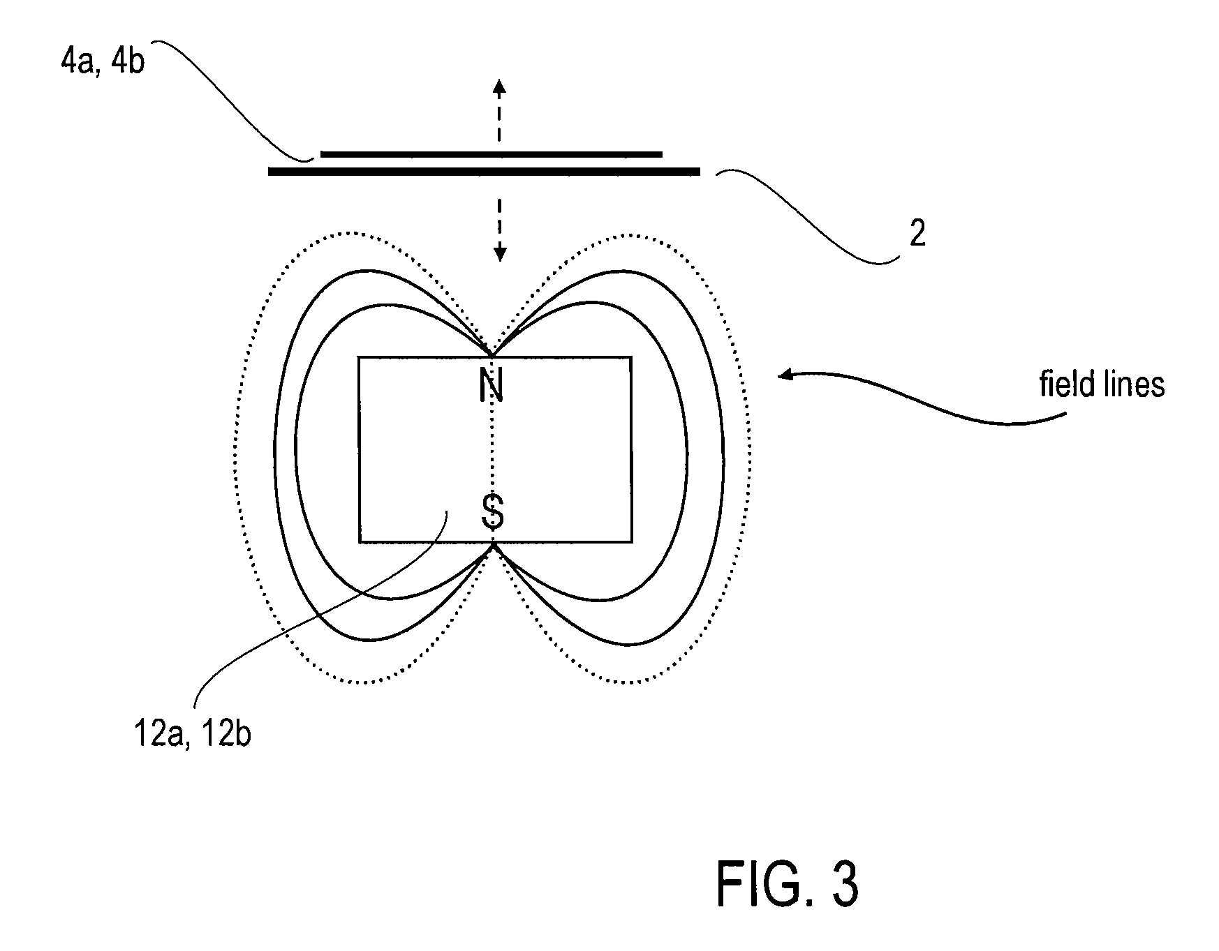
An electrical generator including a magnetic field generator and at least one energy converter for converting energy present in fluid flows into vibrations or oscillations. The converter includes a flexible membrane having at least two fixed ends. The membrane vibrates when subject to a fluid flow. One of the electrical conductor and the magnetic field generator is attached to the membrane and configured to move with the membrane. The vibration of the membrane caused by the fluid flow causes a relative movement between the electrical conductor and the applied magnetic field. The relative movement causes a change in the strength of the magnetic field applied to the electrical conductor, and the change in the strength of the magnetic field applied to the electrical conductor induces a current flowing in the conductor.

Description

FILED OF DISCLOSURE[0001]This application generally relates to harvesting energy from flowing fluids, and more specifically, to a unique design of an energy converter and generator that induce oscillations by flowing fluids and utilize the oscillations to produce electricity.BACKGROUND AND SUMMARY[0002]The kinetic energy present in flowing fluids, such as wind or water, has been successfully applied towards productive human ends, such as grinding grain or pumping water. Wind-powered generators were developed to harness these fluid flows for the production of electricity. Today, wind-powered generators take on the largely ubiquitous form of a turbine, or rotating airfoil. While these turbine-based wind generators are generally useful in certain open spaces with consistently high-speed winds, drawbacks still exist, such as heavy initial capital costs, low efficiency at all but a narrow range of wind speeds, the lack of cost effectiveness at lower power outputs levels (<1 kW), etc.[...

Claims


Application Information

Patent Timeline
Patent Type & Authority Patents(United States)
IPC IPC(8): F03G7/08
CPCF03B17/06F03D5/00F03D9/00H02K7/1876H02K35/04Y02E10/725Y02B10/30Y02B10/70Y02E10/28Y02E10/70Y02E10/30Y02E10/20Y02E10/72
Inventor FRAYNE, SHAWN M.
Owner HUMDINGER WIND ENERGY
Learn More