Container holder

a container holder and cover technology, applied in the field of containers, can solve the problems of deterioration of the decorative quality of the conventional container holder b>100/b>, the inability to meet the needs of the customer, so as to achieve good decorative

Inactive Publication Date: 2009-08-11
TOYODA GOSEI CO LTD
View PDF21 Cites 3 Cited by
  • Summary
  • Abstract
  • Description
  • Claims
  • Application Information

AI Technical Summary

Benefits of technology

[0011]The present invention has been developed in view of the aforementioned circumstances. It is therefore an object of the present invention to provide a container holder which can satisfy both requirements, good decorativeness and usability, simultaneously.
[0023]Moreover, it is possible to avoid the interference between the rear end of the cover and an inner periphery of the holder body's opening, because the cover moves firstly to the semi-open position when moving from the close position to the open position, as described above. Consequently, the rear end of the cover hardly interferes with the inner periphery of the holder body's opening even when providing a greater swing locus for the cover. Therefore, it is possible to dispose the front end of the cover below the top surface of the holder body when the cover swings to the open position, while keeping the clearance between the rear end of the cover and the inner periphery of the holder body's opening as narrow as possible when the cover swings to the close position. As a result, it is possible to satisfy both requirements, good decorativeness and usability, simultaneously.
[0024]In addition, in the present container holder, not only the cover swings about the first engager relatively to the swing arm, but also it swings along with the swinging swing arm relatively to the holder body. Thus, the cover swings dual-axially. Accordingly, it is possible to move the cover on a smaller swing locus. Consequently, not only it is possible to more securely inhibit the rear end of the cover from interfering with an inner periphery of the holder body's opening, but also it is possible to make the clearance between the rear end of the cover and the inner periphery of the holder body's opening much smaller. Furthermore, the swing arm has the sliding groove. Accordingly, it is possible to move the cover greatly, but on a much smaller swing locus. Consequently, it is possible to make the clearance between the rear end of the cover and the inner periphery of the holder body's opening much smaller when the cover swings to the close position.
[0025]Moreover, when the present container holder further comprises a guide arm having opposite ends, and held swingably to the holder body at one of the opposite ends, in which the cover further has a second engager disposed adjacent to the front end, and held swingably to the guide arm, it is possible to guide the movement of the cover's front end with the guide arm. Accordingly, it is possible to swing the cover smoothly. In this instance, it is preferable that the holder body can have an inner side wall, and a guide for slidably and swingably holding the first engager of the cover, the guide comprising a first arc extending downward from an upper part of the inner side wall as an arc shape substantially, and a second arc continuing from a lower end of the first arc and extending further downward as an arc shape substantially. When the holder body has such a guide, it is possible to guide the movement of the cover with the first arc of the guide when the cover swings from the close position to the semi-open position, and to guide the movement of the cover with the second arc of the guide when the cover swings from the semi-open position to the open position. Consequently, it is possible to swing the cover much more smoothly.
[0026]In addition, when the present container holder further comprises an urging member having opposite ends, held to the holder body at one of the opposite ends, held to the swing arm at the other one of the opposite ends, and urging the swing arm to swing, it is possible to make an operational force required for moving the cover, that is, an operational force required for opening and closing the opening of the holder body, smaller. Accordingly, it is possible to enhance the usability of the present container holder.

Problems solved by technology

However, note herein that container holders provided with covers might turned out to be bulky, because the covers might project greatly outward from the container holders when they open the openings.
However, providing the clearance between the outer periphery of the cover 102 and the inner periphery 111 of the holder body 101's opening 107 might impair the integrity between the cover 102 and the holder body 101 to result in a problem that the decorativeness of the conventional container holder 100 deteriorates.
Moreover, the clearance “a” might result in a problem that thin foreign matters, such as papers, fall down into the holder body 101 through the clearance “a.” In order to solve these problems, it is better not to provide the clearance “a.” Thus, the conventional container holder 100 might suffer from the trade-off circumstances.
In this instance, it might be less likely to hold containers in or remove them from the conventional container holder 101 so that there arises a problem as well that the usability of the conventional container holder 100 deteriorates.
However, the cover 102, which moves greatly, has enlarged its swing locus to result in a problem that the clearance “a” should be furthermore enlarged.
In this arrangement, however, the freedom of designing container holder might degrade, because it is necessary to dispose the top surface of the cover at a position lower than the top surface of the holder body when the cover swings to the close position.
Moreover, there might arise a problem that the decorativeness of container holder is poor, because a step is made between the top surface of the cover and the top surface of the holder body when the cover swings to the close position.

Method used


Image

  • Container holder
  • Container holder
  • Container holder

Examples


example no.1

Example No. 1

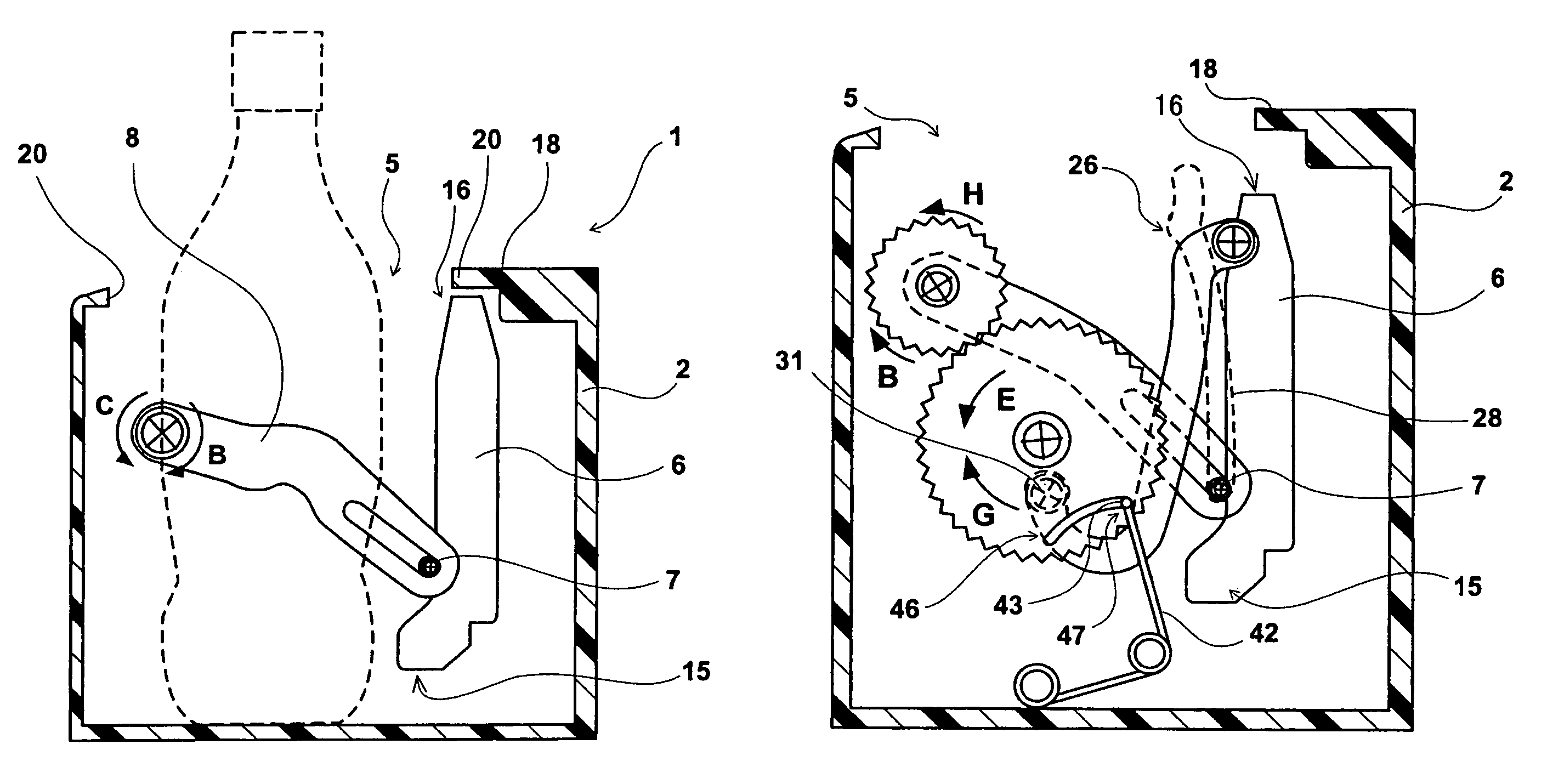
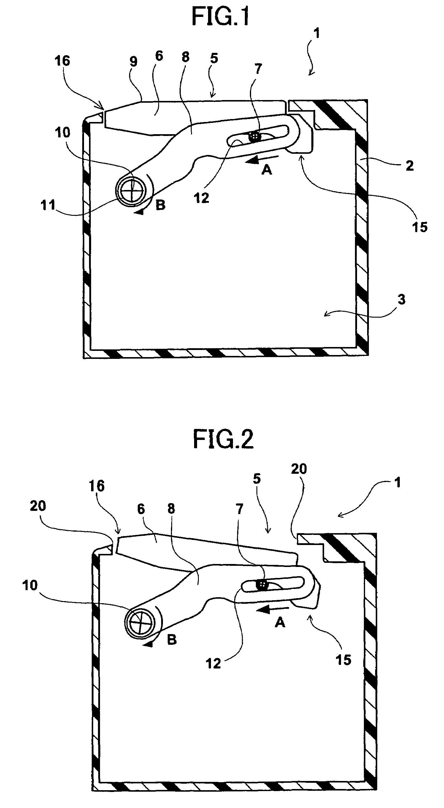
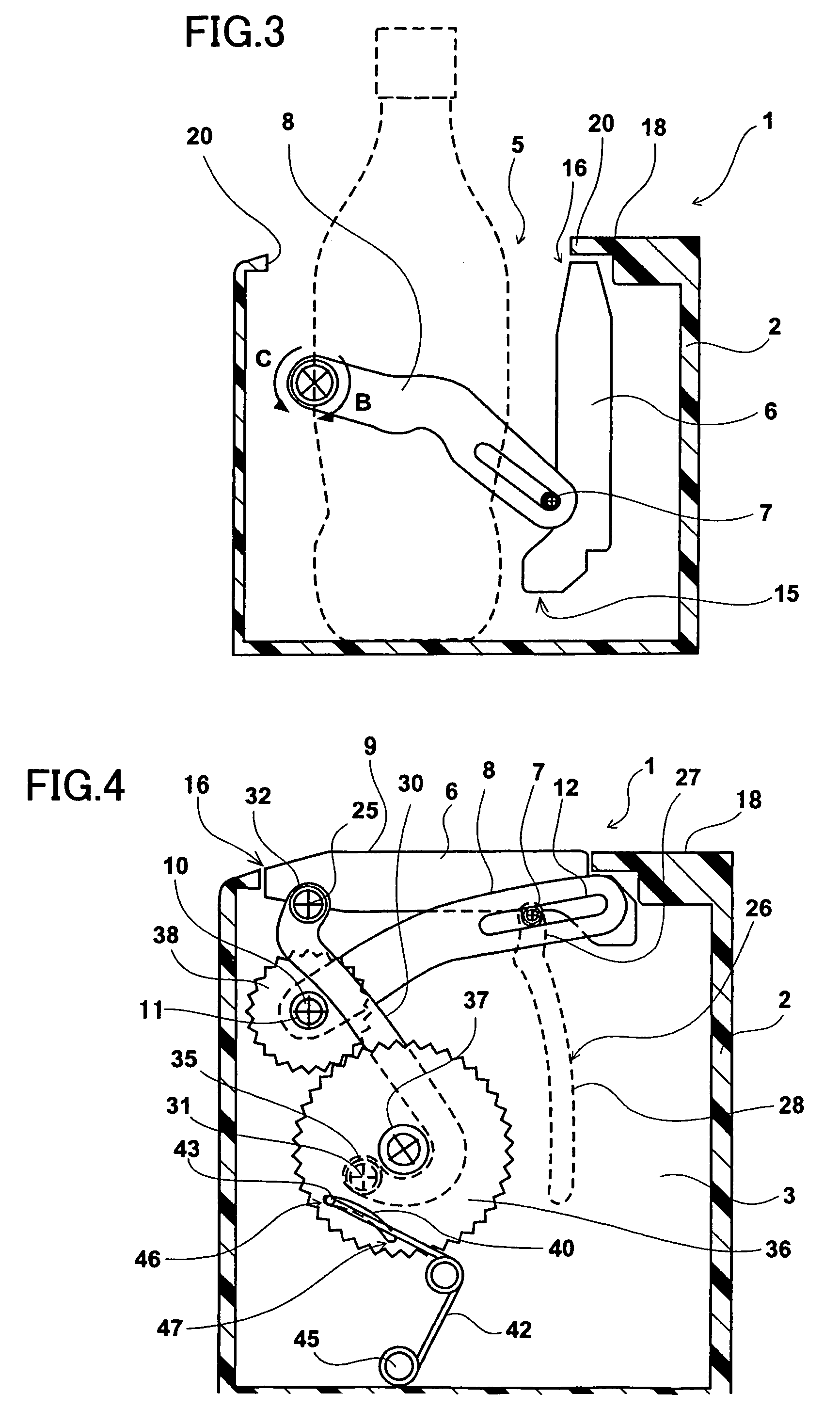
[0038]A container holder according to Example No. 1 of the present invention will be hereinafter described with reference to accompanying FIGS. 1 through 3 which illustrate the container holder schematically. Note that FIG. 1 represents the container holder with its cover positioned at the close position; FIG. 2 represents the container holder with its cover positioned at the semi-open position; and FIG. 3 illustrates the container holder with its cover positioned at the open position.

[0039]A container holder 1 shown in FIGS. 1 through 3 comprises a holder body 2, a cover 6, and a swing arm 8. The holder body 2 is formed as a box shape substantially. Moreover, the holder body 2 is opened upward to form an opening 5, and demarcates an accommodation space 3 within its box-shaped profile.

[0040]The opening 5 of the holder body 2 makes an inlet / outlet port for fitting a container into or removing it from the accommodation space 3 when holding the container with the container...

example no.2

Example No. 2

[0050]A container holder according to Example No. 2 of the present invention will be hereinafter described. FIGS. 4 through 7 illustrate the container holder according to Example No. 2 schematically.

[0051]Specifically, in addition to a modified cover 6, that is, the cover 6 of the container holder 1 according to Example No. 1 which has a second engager (or engagement portion) disposed adjacent to the front end 16, the container holder 1 according to Example No. 2 further comprises a guide arm, a guide, and an urging member (or actuator).

[0052]The container holder 1 according to Example No. 1 comprises the modified cover 6 which has a second engagement portion 25 disposed at the front end 16, as shown in FIGS. 4 through 7. Except for the second engagement portion 25, the modified cover 6 is the same as that of the above-described container holder 1 according to Example No. 1. The second engagement portion 25 is formed as a shaft which projects in the same direction as th...


PUM


Abstract

A container holder includes a holder body, a cover, and a swing arm. The cover has a front end, a rear end, a first engager disposed adjacent to the rear end. The swing arm has a sliding groove extending in a direction crossing the up / down directions of the holder body, holds the first engager of the cover slidably and swingably with the sliding groove, and is held swingably to the holder body at one of the opposite ends. When the swing arm swings the cover from a close position to an open position, the swing arm lets the cover pass firstly a semi-open position, at which the sliding groove guides the cover so as to decline the rear end of the cover, and then lets the cover swing to the open position along with the swinging swing arm.

Description

BACKGROUND OF THE INVENTION[0001]1. Field of the Invention[0002]The present invention relates to a container for holding or accommodating containers for drinks therein.[0003]2. Description of the Related Art[0004]A container holder for holding containers for drinks has been known, container holder which comprises a holder body. The holder body is formed as a box shape substantially, has an opening opened upward, and demarcates an accommodation space. The container holder holds containers, which are fitted into the holder body, within the accommodation space. Such a container holder is usually provided with a cover which opens and closes the opening of the holder body.[0005]Container holders are usually disposed in limited spaces, represented by automotive passenger rooms, for instance. Accordingly, it is needed to form container holders as less bulky shapes as possible. However, note herein that container holders provided with covers might turned out to be bulky, because the covers ...

Claims


Application Information

Patent Timeline
Patent Type & Authority Patents(United States)
IPC IPC(8): A47K1/08
CPCB60N3/101
Inventor KATAGIRI, KATSUHIRO
Owner TOYODA GOSEI CO LTD
Why Eureka
Try Eureka