
System and method for controlling transmission power in wireless local area network

a wireless local area network and transmission power technology, applied in power management, network topologies, wireless commuication services, etc., can solve the problems of difficult to establish a communication link between the ap and the station outside the transmission power range of the ap, and the ap does not recognize the ap information, so as to achieve efficient transmission power control

Inactive Publication Date: 2009-08-04
SAMSUNG ELECTRONICS CO LTD
View PDF9 Cites 32 Cited by
  • Summary
  • Abstract
  • Description
  • Claims
  • Application Information

AI Technical Summary

Benefits of technology

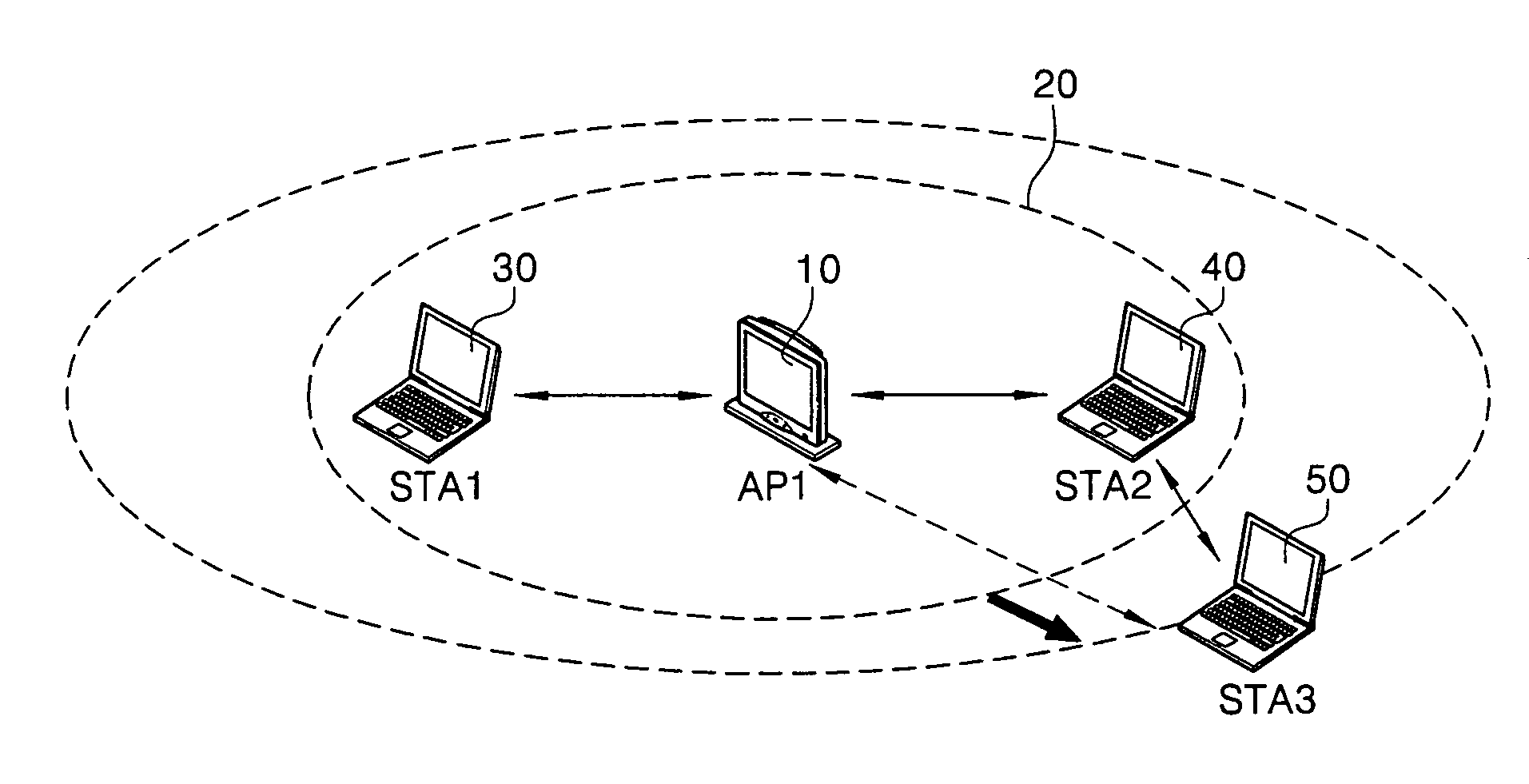
The present invention provides a system and method for controlling transmission power in a wireless local area network (WLAN) that can efficiently control the power of an access point so that a station outside the WLAN service area can associate with it. This is achieved by receiving link margin data of a third station positioned at a hidden node of the WLAN from a second station positioned in a service area and comparing it to preset link margin data to control transmission power. The access point can also switch its mode from an infrastructure mode to an ad-hoc mode and send a beacon to the second station to calculate link margin data of the third station. The technical effects of the invention include efficient control of transmission power and improved connectivity for stations outside the WLAN service area.

Problems solved by technology

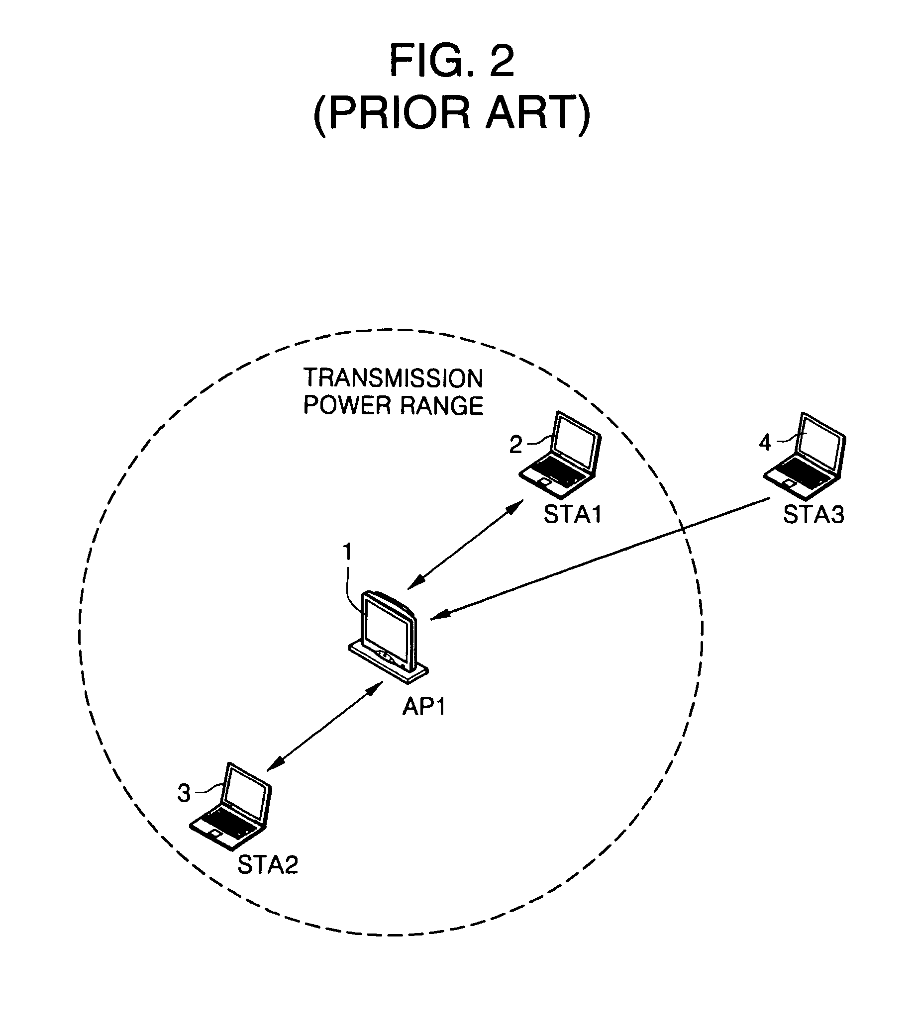
However, a station positioned at a hidden node outside the transmission power range of the AP is unable to correctly receive the beacon information from the AP, which makes it difficult to associate with the AP.
In other words, since the AP is able to receive information from the station outside the transmission power range of the AP, but the transmission power of the AP is insufficient to reach the station outside the transmission power range of the AP, the station outside the transmission power range of the AP does not recognize the AP information.
Accordingly, it is difficult to establish a communication link between the AP and the station outside the transmission power range of the AP.
Further, the AP has the disadvantage of high power loss because the AP maintains a certain transmission power all the time.

Method used


Image

  • System and method for controlling transmission power in wireless local area network
  • System and method for controlling transmission power in wireless local area network
  • System and method for controlling transmission power in wireless local area network

Examples


Embodiment Construction

[0039]The present invention will now be described more fully with reference to the accompanying drawings, in which preferred embodiments of the invention are shown. This invention may, however, be embodied in different forms and should not be construed as limited to the embodiments set forth herein. Rather, these embodiments are provided so that this disclosure will be thorough and complete, and will fully convey the scope of the invention to those skilled in the art.

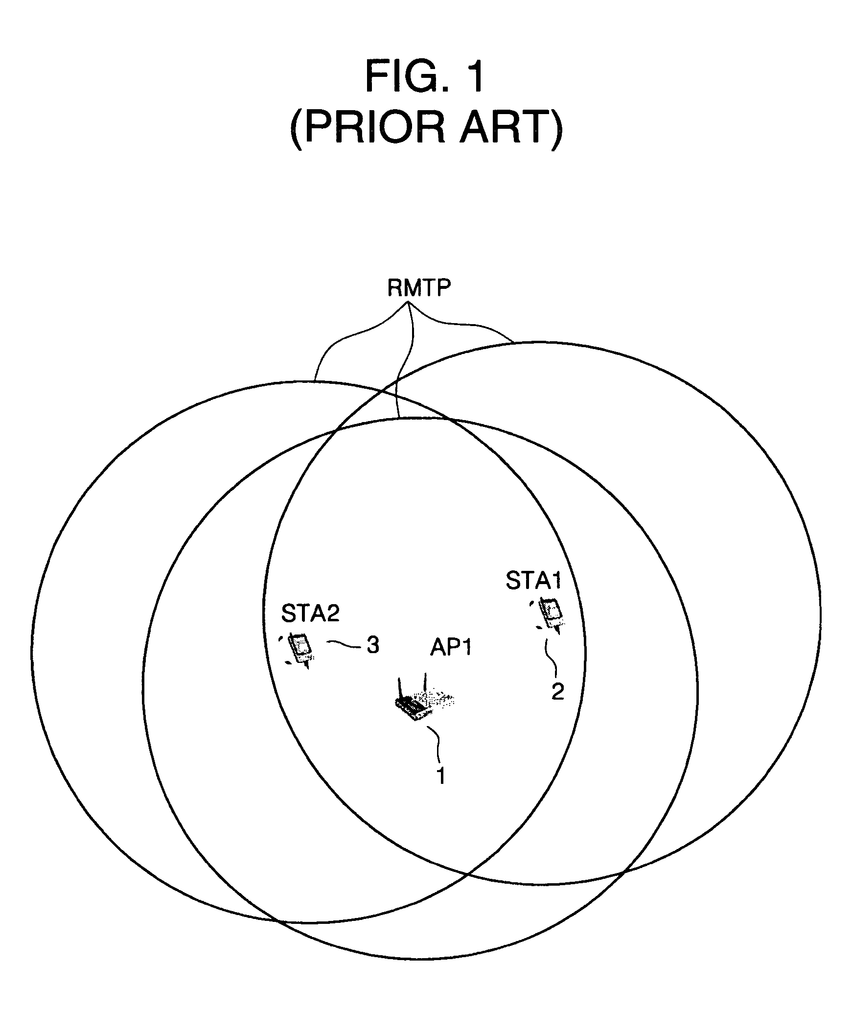
[0040]FIG. 1 is a diagram of the configuration of a WLAN system. As shown in FIG. 1, transmission powers of an AP11, stations STA12, and STA23 are set within regulatory maximum transmission power (RMTP).

[0041]FIG. 2 is a diagram showing the configuration of a system including stations outside a transmission power range of an AP. As shown in FIG. 2, since stations STA12 and STA23 are positioned in a transmission power range of an AP11, the stations STA12 and STA23 may associate with the AP11 by recognizing their maximum ...


PUM


Abstract

Disclosed are a system and method for controlling transmission power in a wireless local area network (WLAN), and more particularly, a system and method for controlling transmission power in a WLAN that are capable of providing a WLAN service to terminals outside a service area by controlling the transmission power in the WLAN. Thus, link margin data of a station positioned at a hidden node of the WLAN is received from another station positioned in a service area, and the received link margin data is compared with preset link margin data for control of the transmission power in the WLAN.

Description

CLAIM OF PRIORITY[0001]This application makes reference to, incorporates the same herein, and claims all benefits accruing under 35 U.S.C. 1.119 from an application for SYSTEM AND METHOD FOR CONTROLLING TRANSMISSION POWER IN WIRELESS LOCAL AREA NETWORK earlier filed in the Korean Intellectual Property Office on 8 Dec., 2004, and there duly assigned Serial No. 2004-103208.BACKGROUND OF THE INVENTION[0002]1. Field of the Invention[0003]The present invention relates to a system and method for controlling transmission power in a wireless local area network (WLAN), and more particularly, to a system and method for controlling transmission power in a WLAN, capable of providing WLAN service to terminals outside a service area by controlling the transmission power in the WLAN.[0004]2. Description of the Related Art[0005]A local area network (LAN) may be largely classified into a wired LAN and a wireless LAN. The largest difference between the two LANs is whether or not a cable is present.[0...

Claims


Application Information

Patent Timeline
Patent Type & Authority Patents(United States)
IPC IPC(8): H04B7/00H04W52/24H04W52/34H04W84/12
CPCH04W52/24H04W52/346H04W84/12H04W88/08
Inventor HWANG, BO-SEUNGYOUN, MYEON-KEE
Owner SAMSUNG ELECTRONICS CO LTD
Learn More