
Tool cabinet

a tool cabinet and tool body technology, applied in the field of tool cabinets, can solve the problems of wasting time, wasting space, and wasting tools, and achieve the effects of saving much room free of use, simple structure, and simple and convenient assembly

Inactive Publication Date: 2009-07-14
ZHEJIANG LIMAI METAL PRODS
View PDF20 Cites 7 Cited by
  • Summary
  • Abstract
  • Description
  • Claims
  • Application Information

AI Technical Summary

Benefits of technology

"The invention is a foldable tool cabinet with a simple structure that can be easily disconnected and assembled. The case body is composed of loosely interconnected case boards that can be folded and a upright column. The upper cover and bottom board can be folded and stored in a convenient way. The case boards have slots and hinges for easy assembly. The tool cabinet can be closed and aesthetically pleasing with a closed upper cover. The invention also includes a shelf and grip blocks for easy access and use. The technical effects of the invention are a simplified structure, easy disconnection and assembly, and a closed upper cover for aesthetical purposes."

Problems solved by technology

The main structure of the conventional tool cabinet is typically one whole body, which is heavy and not easy to carry.
There are complicated structures, such as mosaic assembly type, screw lock type etc, but it is disadvantageous in using tool to disconnect and assemble them.
It is fussy and time-consuming.
On the other hand, when the tool cabinet is free of use, it will still take much space.

Method used


Image

  • Tool cabinet
  • Tool cabinet
  • Tool cabinet

Examples


Embodiment Construction

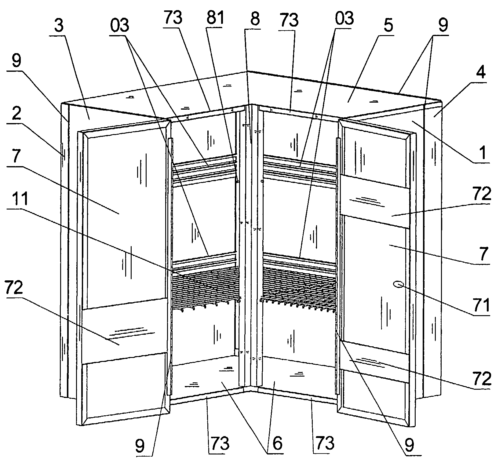
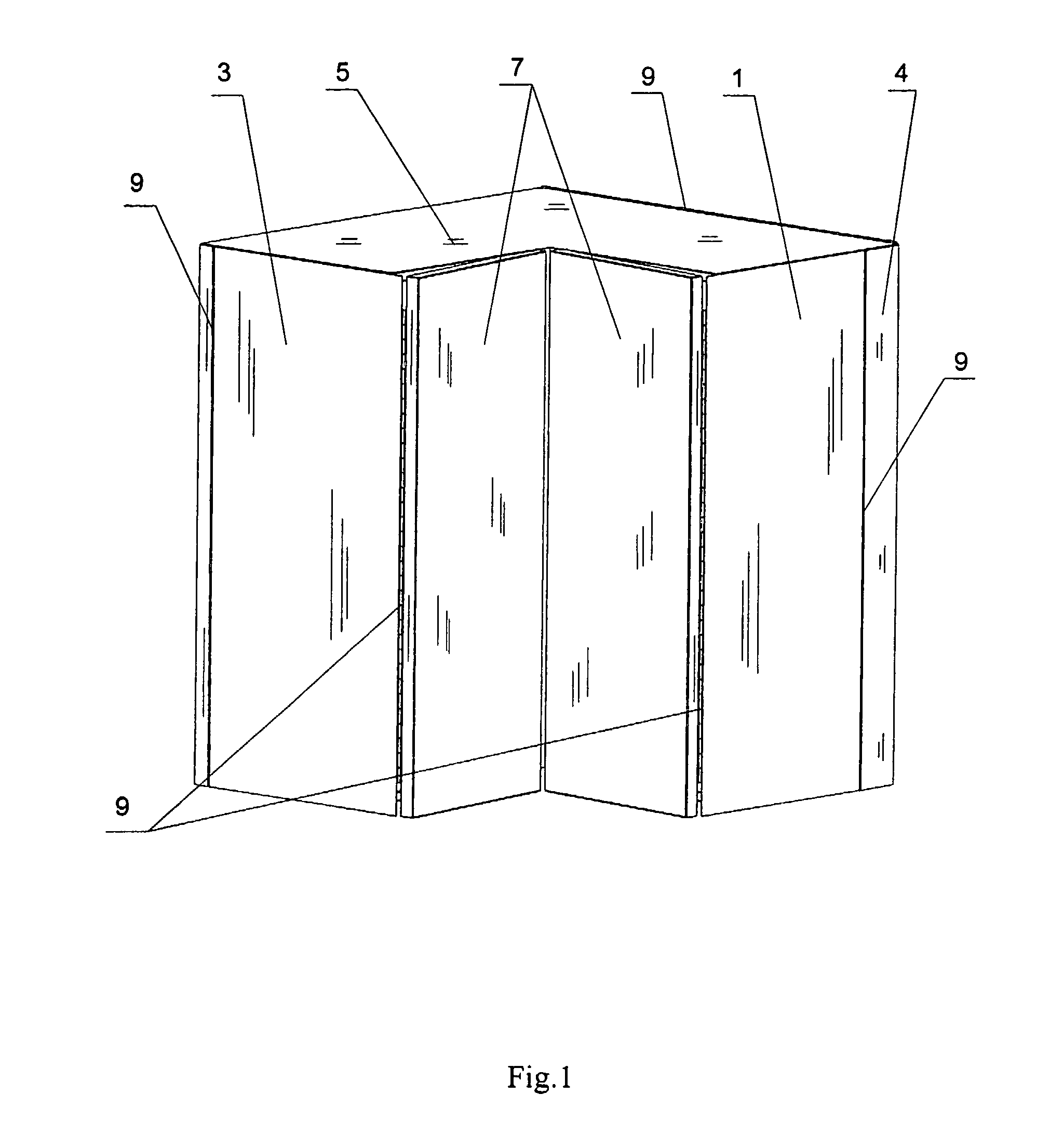
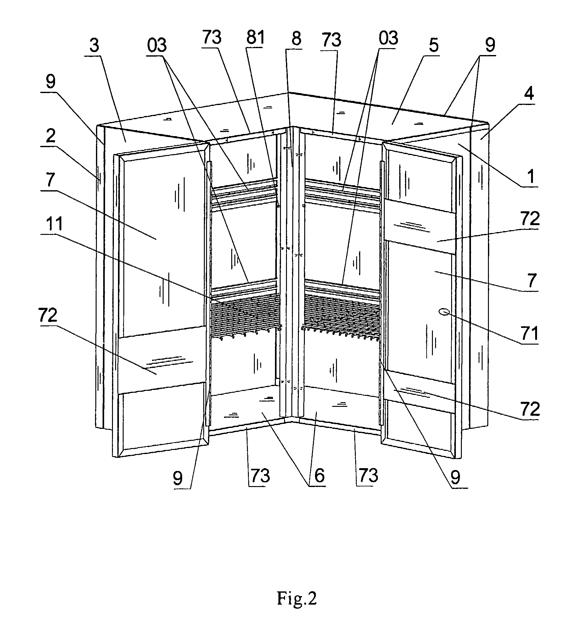
[0036]As shown in FIG. 1 and FIG. 2, the tool cabinet according to the embodiment of the invention comprises the front board 1, the back board 2, the left board 3, the right board 4, the upper cover 5, the bottom board 6, the door boards 7, the shelf 11 and the L-type upright column 8. The structure of the front board 1 is the same as that of the left board 3 and the back board 2 and the right board 4. The door lock 71 is set on the door board 7 with several tool slots 72 set at its inner side. One side of the right board 4 loosely and rotatably connects with the front board 1 and with the back board 2 on the other side. The other side of the back board 2 loosely and rotatably connects with the left board 3. The above-mentioned loose connection is inwardly rotatable connection by the hinges 9. As shown in FIG. 7 and FIG. 8, single hems 31 are set on one side of the front board 1 and the left board 3. Slot-type hems 41 are set on the back board 2 and the right board 4. It is convenie...


PUM

PropertyMeasurementUnit
volumeaaaaaaaaaa
timeaaaaaaaaaa
compatibilityaaaaaaaaaa

Abstract

A tool cabinet including an upper cover, a bottom board, a case body and a shelf accessory. The case body includes rotatably interconnected case boards, which are foldable with each other. The upper cover and the bottom board are loosely rabbeted into the case body. Without disconnecting each case board, each case board can be folded by pulling out a pin in the upper cover, turning over the upper cover, then taking out the shelf and the upright column, releasing the block rabbeting, and folding the case boards.

Description

CROSS-REFERENCE TO RELATED APPLICATIONS[0001]The present application claims priority under 35 USC 119 to Chinese Patent Application No. 2005-10050646.1 filed on Jul. 8, 2005 the entire contents of which are hereby incorporated by reference.FIELD OF THE INVENTION[0002]The present invention relates to a tool cabinet, especially a tool cabinet that can be folded and assembled conveniently with pin joint member loosely interconnecting each face board.DESCRIPTION OF BACKGROUND ART[0003]A tool cabinet is mainly used for uniform management of materials in all trades. The main structure of the conventional tool cabinet is typically one whole body, which is heavy and not easy to carry. There are complicated structures, such as mosaic assembly type, screw lock type etc, but it is disadvantageous in using tool to disconnect and assemble them. For the assembled tool cabinet of large volume, which is not fit for carrying as a whole, once carrying, it is necessary to disconnect by the aid of tool...

Claims


Application Information

Patent Timeline
Patent Type & Authority Patents(United States)
IPC IPC(8): A47B47/00
CPCA47B47/0075A47B43/00
Inventor ZHENG, YING
Owner ZHEJIANG LIMAI METAL PRODS
Learn More