
Electrical cabinet assembly and seal assembly therefor

a cabinet assembly and sealing technology, applied in the field of electric cabinet assembly and sealing assembly therefor, can solve the problems of generating flames and flying debris, arc formation rapidly expanding gases, and substantial arc in the arc chamber of the circuit breaker

Active Publication Date: 2009-07-07
EATON INTELLIGENT POWER LIMITED
View PDF17 Cites 32 Cited by
  • Summary
  • Abstract
  • Description
  • Claims
  • Application Information

AI Technical Summary

Benefits of technology

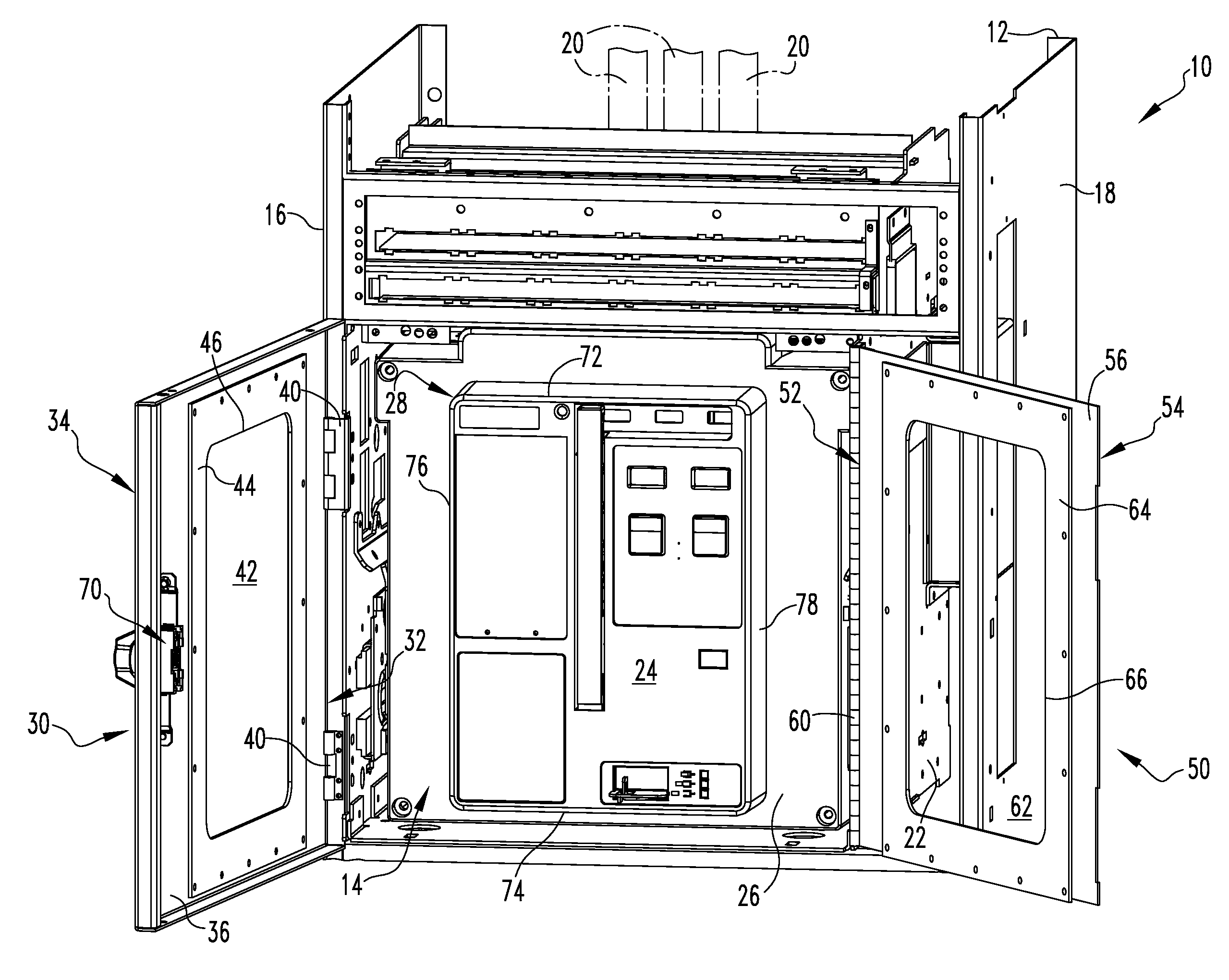
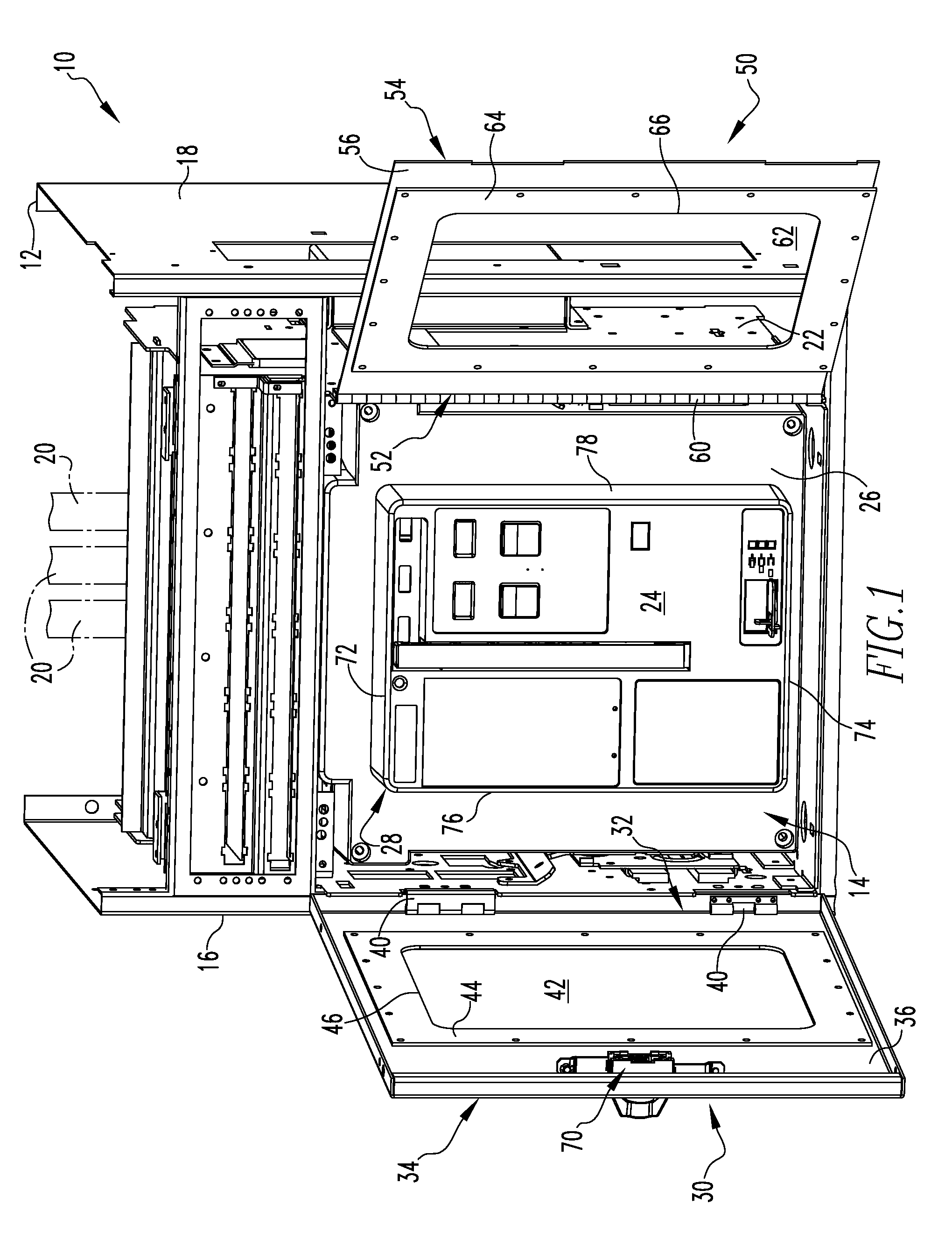
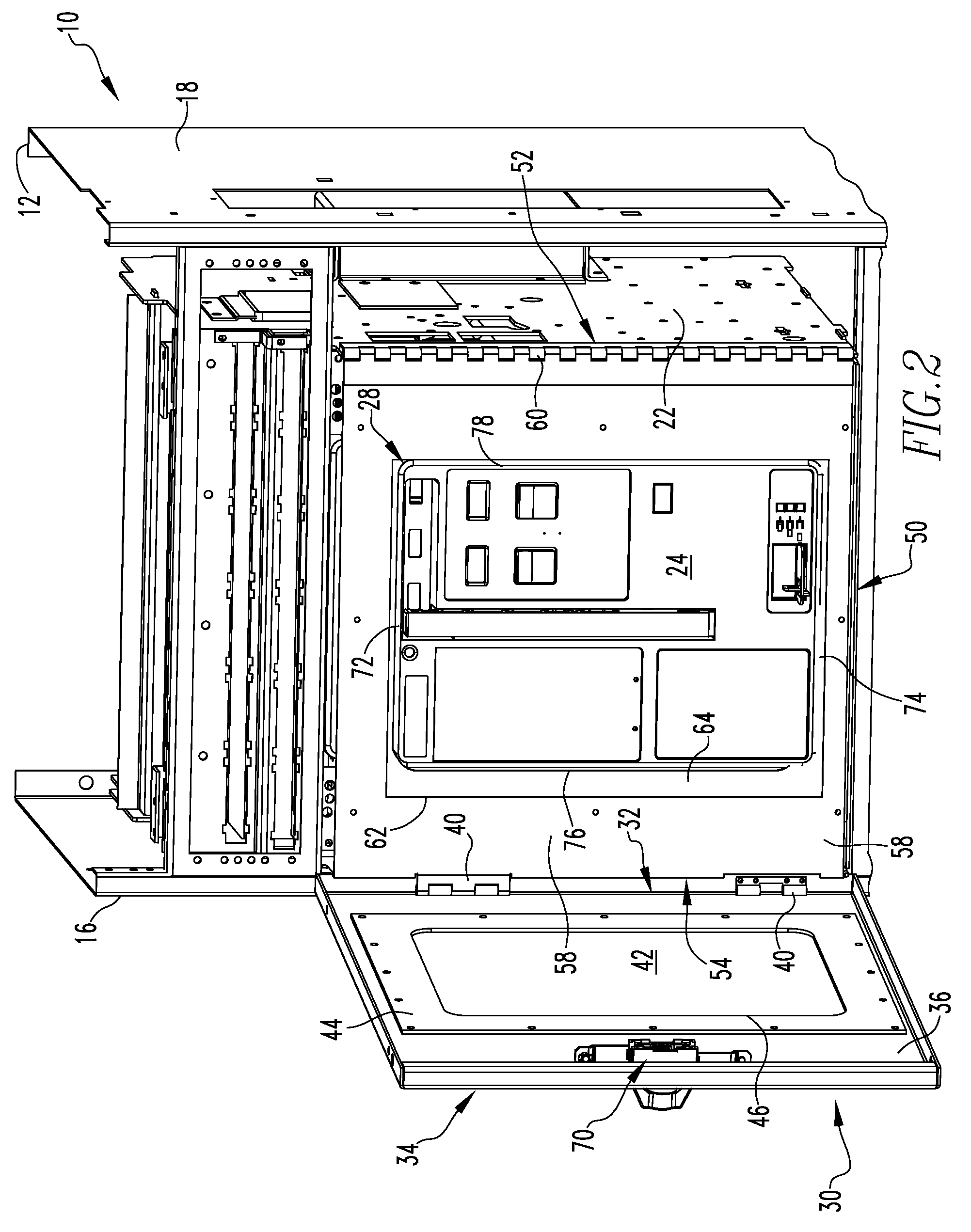
[0019]The circuit breaker may be movable between a first position in which the circuit breaker is in electrical contact with the number of conductors and a second position in which the circuit breaker is not in electrical contact with the number of conductors. The seal assembly may substantially seal all of the nose portion of the circuit breaker when the circuit breaker is disposed at or between the first and second positions, thereby substantially sealing the interior of the electrical enclosure from the exterior of the electrical enclosure.

Problems solved by technology

A high current fault interruption, for example, typically results in a substantial arc in the arc chamber of the circuit breaker.
The arc forms rapidly expanding gases, and may generate flames and flying debris comprised of molten metal particles and fragments of various circuit breaker components.
If the electrical enclosure is not sealed with respect to the circuit breaker, the arc gases and related debris can undesirably be expelled outwardly from the enclosure between the front access door and the circuit breaker, potentially causing injury to an operator or other person(s) adjacent the enclosure.
However, known seal assemblies and / or seals therefor interfere with the ability to rack the circuit breaker in and out through the front access door.

Method used


Image

  • Electrical cabinet assembly and seal assembly therefor
  • Electrical cabinet assembly and seal assembly therefor
  • Electrical cabinet assembly and seal assembly therefor

Examples


Embodiment Construction

[0031]Directional phrases used herein, such as, for example, left, right, front, back, top, bottom and derivatives thereof, relate to the orientation of the elements shown in the drawings and are not limiting upon the claims unless expressly recited therein.

[0032]As employed herein, the term “fastener” refers to any suitable connecting or tightening mechanism expressly including, but not limited to, screws, bolts and the combinations of bolts and nuts (e.g., without limitation, lock nuts) and bolts, washers and nuts.

[0033]As employed herein, the statement that two or more parts are “coupled” together shall mean that the parts are joined together either directly or joined through one or more intermediate parts.

[0034]As employed herein, the term “number” refers to the quantity one or an integer greater than one (i.e., a plurality).

[0035]As employed herein, the term “circuit breaker” refers to an electrical circuit breaker that may be drawn into and out of an enclosure (e.g., without l...


PUM


Abstract

A seal assembly for an electrical enclosure having a draw-out circuit breaker and a number of conductors is provided having a movable first seal member and a movable second seal member. The circuit breaker includes a protruding nose portion that is engaged by the first and second seal members in a manner that sealingly engages the nose portion. The arrangement of the first and second seal members and the nose portion provides for the sealing engagement to be maintained when the circuit breaker is moved from a first position in which the circuit breaker is not electrically connected to the number of conductors and a second position in which the circuit breaker is electrically connected to the number of conductors.

Description

BACKGROUND OF THE INVENTION[0001]1. Field of the Invention[0002]The invention relates generally to electrical switching apparatus and, more particularly to electrical enclosures for electrical switching apparatus, such as draw-out circuit breakers. The invention also relates to seal assemblies for electrical enclosures.[0003]2. Background Information[0004]Switchgear for electric power distribution systems includes electrical switching apparatus and their line and load terminations together with related equipment mounted in an electrical enclosure (typically a metal cabinet). Switchgear used in sections of electric power distribution systems operating at voltages up through 690 volts is classified as low voltage switchgear (according to international standards, although the ANSI standard for low voltage is a maximum of 600 volts). Typically, the electrical switching apparatus is a circuit breaker, but other switching apparatus such as, for example, network protectors, disconnect swit...

Claims


Application Information

Patent Timeline
IPC IPC(8): H02B11/00H01H33/02
CPCH02B11/02
Inventor COOMER, JARROD L.ABRAHAMSEN, MICHAEL H.METCALF, DAVID A.FAIR, TIMOTHYMOORE, STANLEY E.
Owner EATON INTELLIGENT POWER LIMITED
Learn More