
Method of increasing gas exchange of a lung

a technology of gas exchange and lung, which is applied in the field of lung disease treatment, can solve the problems of reducing the capacity and efficiency of the lung, so as to achieve the effect of improving the strength of the airway

Inactive Publication Date: 2009-07-07
BOSTON SCI SCIMED INC
View PDF355 Cites 250 Cited by
  • Summary
  • Abstract
  • Description
  • Claims
  • Application Information

AI Technical Summary

Benefits of technology

This approach improves gas exchange and lung efficiency without the invasive risks of traditional surgery, providing a safer and more effective treatment for pulmonary diseases by strengthening airway walls and preventing collapse during exhalation.

Problems solved by technology

Patients with pulmonary disease, such as chronic bronchitis, and emphysema have reduced lung capacity and efficiency, typically due to the breakdown of lung tissue.
In cases of severe chronic pulmonary disease, such as emphysema, lung tissue is destroyed, reducing the strength of the airways.
This reduction in strength of the airway walls allows the walls to become “floppy” thereby losing their ability to remain open during exhalation.
In this diseased state, the patient suffers from the inability to get the air out of their lungs due to the collapse of the airways during exhalation.
Within the confines of the chest cavity, this overinflation restricts the in-flow of fresh air and the proper function of healthier tissue, resulting in significant breathlessness.
When severe emphysema patients take in as much air as their chest cavity can accommodate, they still have insufficient gas exchange because their chest is full of non-functional air filling large cavities in the lungs.
A wide variety of drugs are available for treating the symptoms of pulmonary disease, but none are curative.
Unfortunately, a large number of patients are not responsive to these medications or become non-responsive after prolonged periods of treatment.
This surgery has substantial risks of serious post-operative complications, such as pneumothorax, and requires an extended convalescence.

Method used


Image

  • Method of increasing gas exchange of a lung
  • Method of increasing gas exchange of a lung
  • Method of increasing gas exchange of a lung

Examples


Embodiment Construction

[0093]In the following description, like reference numerals refer to like parts.

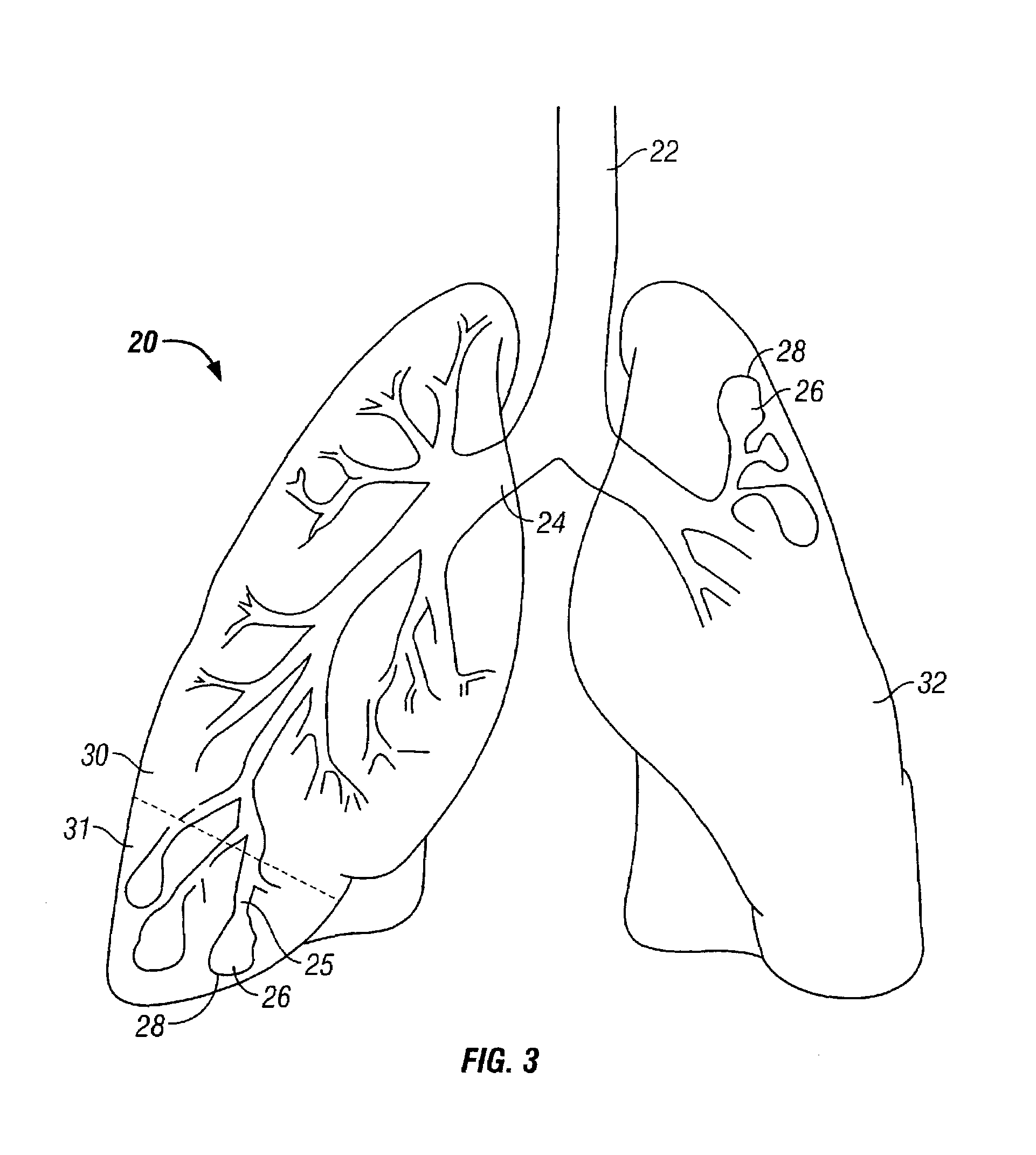
[0094]FIG. 3 illustrates human lungs 20 having a left lung 30 and a right lung 32. A diseased portion 31 is located at the lower portion or base of the left lung 30 (indicated by the volume of the lung below the dashed line on the left lung). In some cases, the diseased portions of an unhealthy lung are not generally located in discrete areas. That is, the diseased portions may not be distributed heterogeneously, and are more homogeneous.

[0095]As illustrated in FIG. 3, the trachea 22 extends down from the larynx and conveys air to and from the lungs. The trachea 22 divides into right and left main bronchi 24, which in turn form lobar, segmental, and sub-segmental bronchi or bronchial passageways. Eventually, the bronchial tree extends to the terminal bronchiole. At the terminal bronchiole, alveolar sacs 26 contain alveoli 28 that perform gas exchange as humans inhale and exhale.

[0096]FIG. 4 illustrates a...


PUM


Abstract

Methods of increasing gas exchange performed by the lung by damaging lung cells, damaging tissue, causing trauma, and / or destroying airway smooth muscle tone with an apparatus inserted into an airway of the lung. The damaging of lung cells, damaging tissue, causing trauma, and destroying airway smooth muscle tone with the apparatus may be any one of or combinations of the following: heating the airway; cooling the airway; delivering a liquid to the airway; delivering a gas to the airway; puncturing the airway; tearing the airway; cutting the airway; applying ultrasound to the airway; and applying ionizing radiation to the airway.

Description

[0001]This is a continuation application of U.S. application Ser. No. 09 / 349,715, filed Jul. 8, 1999 now U.S. Pat. No. 6,488,673, which is a continuation-in-part application of U.S. application Ser. No. 09 / 260,401 filed Mar. 1, 1999, which is a continuation-in-part of application Ser. No. 09 / 003,750 filed Jan. 7, 1998, which is a continuation-in-part of application Ser. No. 08 / 833,550 filed Apr. 7, 1997. U.S. application Ser. No. 09 / 349,715, filed Jul. 8, 1999, now U.S. Pat. No. 6,488,673 is also a continuation-in-part of application Ser. No. 08 / 994,064 filed Dec. 19, 1997, which is a continuation-in-part of application Ser. No. 08 / 833,550 filed Apr. 7, 1997. U.S. application Ser. No. 09 / 349,715, filed Jul. 8, 1999, now U.S. Pat. No. 6,488,673 is also a continuation-in-part of application Ser. No. 09 / 224,937 filed Dec. 31, 1998, which is a continuation-in-part application Ser. No. 08 / 833,550 filed Apr. 7, 1997. U.S. application Ser. Nos. 09 / 260,401; 09 / 224,937; 09 / 003,750; 08 / 994,06...

Claims


Application Information

Patent Timeline
Patent Type & Authority Patents(United States)
IPC IPC(8): A61M31/00A61B17/00A61B17/22A61B18/00A61B18/04A61B18/08A61B18/14A61B18/18A61M25/00A61M29/00A61N1/06A61N1/40
CPCA61B18/00A61N1/403A61B18/1492A61M25/0043A61M29/02A61N1/06A61B18/14A61B2017/00115A61B2017/22062A61B2018/00214A61B2018/00541A61B2018/044A61B2018/046A61B2018/1407A61B2018/1807A61M2025/0096A61M2210/1039A61B18/08
Inventor LAUFER, MICHAEL D.THOMPSON, DAVID P.LOOMAS, BRYAN E.
Owner BOSTON SCI SCIMED INC
Learn More