
Tire for two-wheeled vehicle comprising an anti-vibration means

a two-wheeled vehicle and anti-vibration technology, applied in the field of tires, can solve the problems of tire that does not have anti-vibration technology, different types of vibration, etc., and achieve the effect of improving performan

Inactive Publication Date: 2009-07-07
MICHELIN RECH & TECH SA
View PDF30 Cites 4 Cited by
  • Summary
  • Abstract
  • Description
  • Claims
  • Application Information

AI Technical Summary

Benefits of technology

[0007]The present invention is therefore directed at providing a tire, in particular a tire for a front wheel of a vehicle of the two-wheeled type, having improved performance with regard to the vibratory behavior, in particular the shimmy.
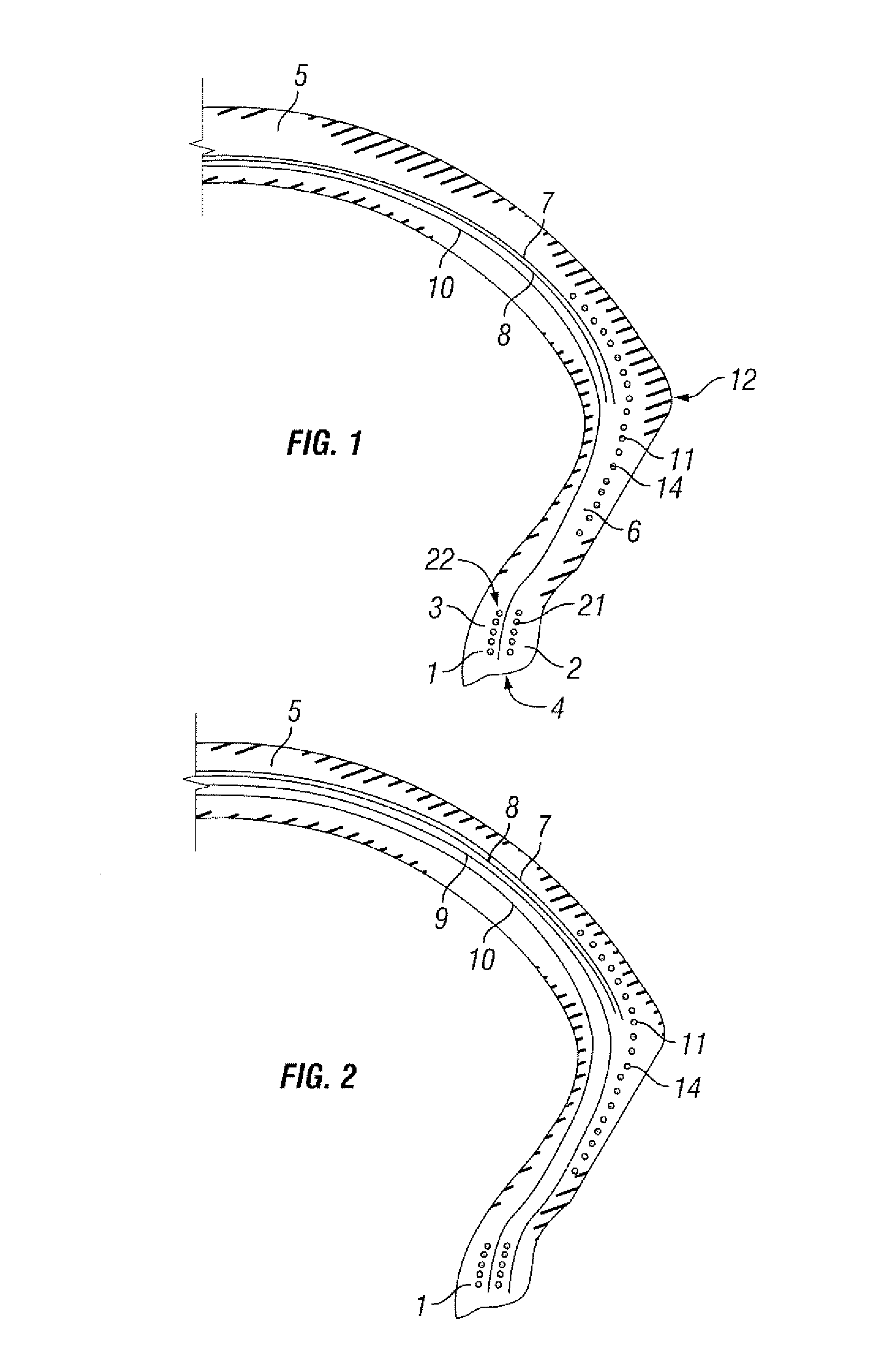
[0015]According to conventional practice, generally increasing the rigidity of the transition or o inflexion zone is avoided since all the rigidities are then adversely affected. This results in a reduction in comfort and durability to impermissible levels. According to the invention, the presence of the anti-vibration means at a precise location and its original structure make it possible to affect in particular the transverse rigidity, without having a significantly adverse effect on the radial and longitudinal rigidity. This is a major characteristic, which makes it possible to fight the phenomenon of shimmy in a truly effective manner. The subject of the present invention is therefore intended above all for use on the front wheel of a two-wheeled vehicle. It may furthermore also be used for the rear wheel or for both.
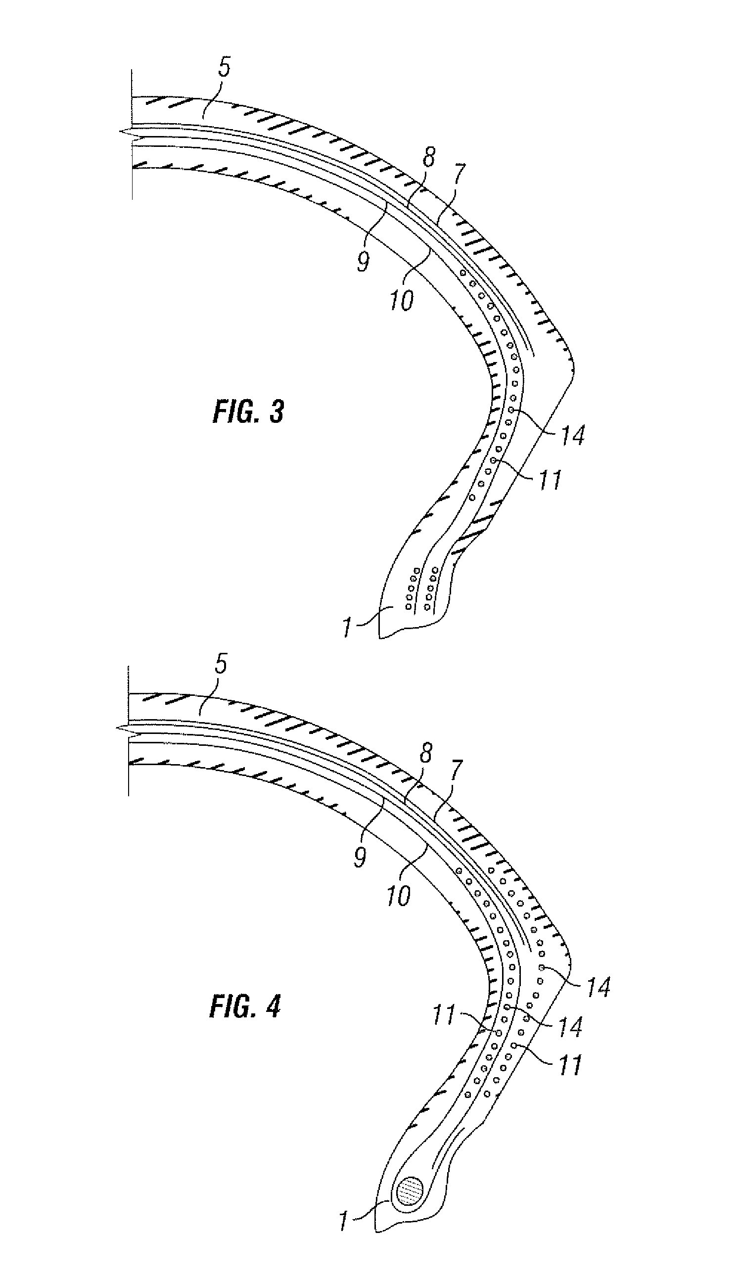
[0016]The material constituting the cord(s) of the winding of the anti-vibration means (for example aramide, metal, glass fiber, polyester, etc), the types of rubber mixes in which the cords are arranged, the density of the cords and the number of windings, affects the transverse rigidity of the tire while retaining substantially a certain stability of the other rigidities of the tire such as the vertical and longitudinal rigidity. The anti-vibration means therefore permits separation of the transverse rigidity from the other rigidities. Furthermore, favorable results are obtained for vibrations such as kick-back, waving, stability of the profile to centrifugation (wear, stability), etc.
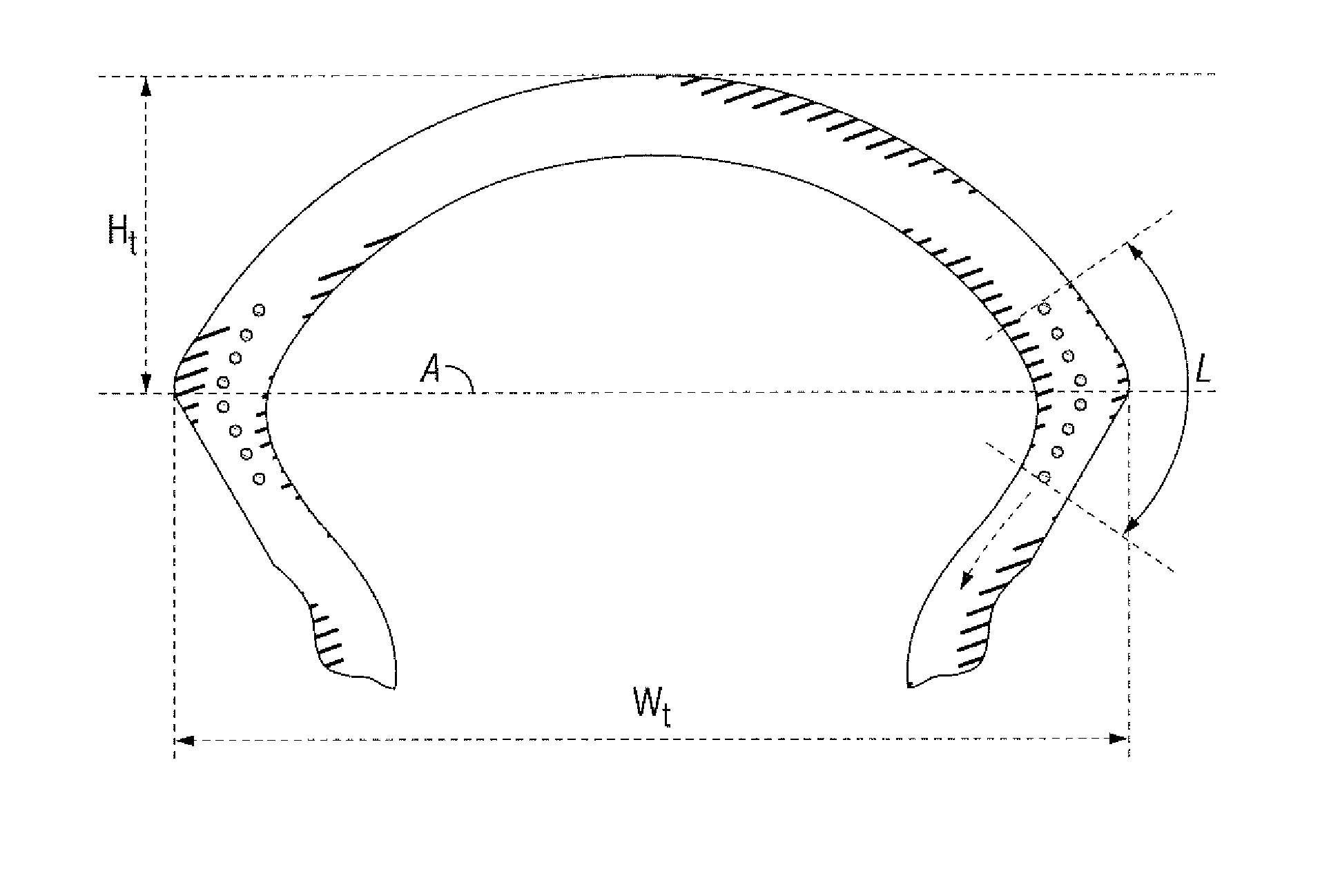
[0020]The present invention also provides for the use of a substantially peripheral anti-vibration means to reduce the generation of shimmy-type vibrations of the in a tire for a two-wheeled vehicle comprising at least one reinforcement structure of carcass type anchored on either side of the tire in a bead the base of which is intended to be mounted on a rim seat, each bead being extended radially towards the outside by a sidewall, the sidewalls joining radially towards the outside a tread, and having a Ht / Wt ratio which is greater than 0.15, the reinforcement structure extending circumferentially from the beads towards said sidewalls. The tire further comprises a transition zone corresponding substantially to the change from the lateral portion of the tread to the sidewall; said anti-vibration means being arranged circumferentially in said transition zone and extending radially substantially radially outward towards the crown and extending substantially radially inward in the sidewall.
[0030]The present invention furthermore provides a reinforcement structure for tires. It is furthermore desirable for this structure to lend itself easily to automated manufacture.

Problems solved by technology

In vehicles of the two-wheeled type, such as motorcycles, scooters and others, the different types of vibration such as those originating from the engine, from travel, imperfections in the road, etc, are difficult to dampen, so they are for the most part transmitted to the occupants of the vehicle.
The result may be a certain amount of discomfort, which may itself be a source of fatigue if use is prolonged, in particular if the levels of vibrations are rather high.
Furthermore, there are nowadays tires that do not have the conventional upturn of the carcass ply around a bead wire, or even a bead wire, in the conventional sense of this element.

Method used


Image

  • Tire for two-wheeled vehicle comprising an anti-vibration means
  • Tire for two-wheeled vehicle comprising an anti-vibration means
  • Tire for two-wheeled vehicle comprising an anti-vibration means

Examples


Embodiment Construction

[0044]In the present specification, the term “cord” designates very generally both monofilaments and multifilaments, or assemblies such as cables, plied yarns or alternatively any type of equivalent assembly, and this, whatever the material and the treatment of these cords, for example surface treatment or coating or pre-sizing to promote adhesion to the rubber. “Radially outward” or “radially upper” means towards the largest radii. “Elasticity modulus” of a rubber mix is understood to mean a secant modulus of extension obtained at a uniaxial deformation of extension of the order of 10% at ambient temperature.

[0045]A reinforcement or reinforcing structure of carcass type will be said to be radial when its cords are arranged at 90°, but also, according to the terminology in use, at an angle close to 90°.

[0046]It is known in the prior art that carcass ply or plies is / are turned up about a bead wire. The bead wire then performs the function of anchoring the carcass, that is to say, tak...


PUM

PropertyMeasurementUnit
angleaaaaaaaaaa
angleaaaaaaaaaa
heightaaaaaaaaaa

Abstract

A tire comprising at least one reinforcement structure of carcass type anchored on either side of the tire in a bead, the base of which is intended to be mounted on a rim seat, each bead being extended radially outward by a sidewall, the sidewalls extending radially towards outward to join a tread, the reinforcement structure extending circumferentially from the bead towards said sidewall, an anchoring zone for the reinforcement structure, said tire furthermore comprising an anti-vibration means arranged circumferentially in the junction zone of the shoulder and the sidewall.

Description

CROSS-REFERENCE TO RELATED APPLICATIONS[0001]This application is a continuation of International Application No. PCT / EP01 / 08567, filed Jul. 25, 2001 and further claims priority to French Patent Application No. 00 / 10290, filed Jul. 31, 2000.BACKGROUND OF THE INVENTION[0002]The present invention relates to tires. More particularly, it relates to a tire, in particular for a vehicle of the two-wheeled type, comprising an anti-vibration means.[0003]In vehicles of the two-wheeled type, such as motorcycles, scooters and others, the different types of vibration such as those originating from the engine, from travel, imperfections in the road, etc, are difficult to dampen, so they are for the most part transmitted to the occupants of the vehicle. These vibrations may occur in the vertical, longitudinal or transverse directions. The result may be a certain amount of discomfort, which may itself be a source of fatigue if use is prolonged, in particular if the levels of vibrations are rather hi...

Claims


Application Information

Patent Timeline
Patent Type & Authority Patents(United States)
IPC IPC(8): B60C9/22B29D30/06B29D30/38B60C13/00B29D30/10B60C9/02B60C9/09B60C9/18B60C15/00B60C15/06
CPCB60C9/09B60C9/22B60C15/0018B60C15/06Y10T152/10783Y10T152/10864Y10T152/10828
Inventor PROST, PASCALVALLE, ALAIN
Owner MICHELIN RECH & TECH SA
Learn More