Conveying equipment and inspection device

a technology of conveying equipment and inspection devices, which is applied in the direction of application, liquid handling, and closures using stoppers, can solve the problems of difficult inspection and inability to clear the rubber stoppers, and achieve the effect of preventing the failure of conveying objects

Inactive Publication Date: 2009-06-30
DAIICHI JITSUGYO VISWILL
View PDF29 Cites 17 Cited by
  • Summary
  • Abstract
  • Description
  • Claims
  • Application Information

AI Technical Summary

Benefits of technology

[0008]According to the first invention, by the aligning means, the objects to be conveyed such as rubber stoppers having a complicated shape are aligned in tandem. At this time, the rubber stoppers placed on a spiral track move on the track and are aligned in tandem, while the rubber stoppers themselves rotate, because of torsional vibration. Thereafter, the aligned rubber stoppers are conveyed not by vibration but by the force generated by jet compressed air. Thus, the conveying means is free of any vibration, and therefore, it becomes possible to mount an inspection camera or the like on the conveying means and to inspect without any vibration. As a result, even when the objects are aligned preliminarily by using aligning means such as a vibratory parts feeder, the inspection area is free of any influence thereof, and thus, a conveying apparatus enabling accurate inspection can be provided.
[0022]According to the eighth invention, when a predetermined number of rubber stoppers are retained by the retaining means, vibration of the feeding means is stopped, so that transfer from the feeding means to the conveying means is stopped. Accordingly, it follows that only a prescribed number of rubber stoppers are supplied to the conveying means that blows compressed air to the rubber stoppers. As a result, such a situation that the conveying means is forced to convey rubber stoppers exceeding the prescribed number at one time does not occur, and therefore, failure in conveying the objects can be prevented.

Problems solved by technology

Therefore, a CCD (Charge Coupled Device) camera at the inspecting portion vibrates, and clear imaging of the rubber stoppers becomes impossible.
This makes accurate inspection difficult.

Method used


Image

  • Conveying equipment and inspection device
  • Conveying equipment and inspection device
  • Conveying equipment and inspection device

Examples


Embodiment Construction

[0042]One embodiment of the present invention will be described in the following with reference to the figures. In the following description, same parts are denoted by same reference characters. Names and functions of these parts are also the same. Therefore, detailed description thereof will not be repeated.

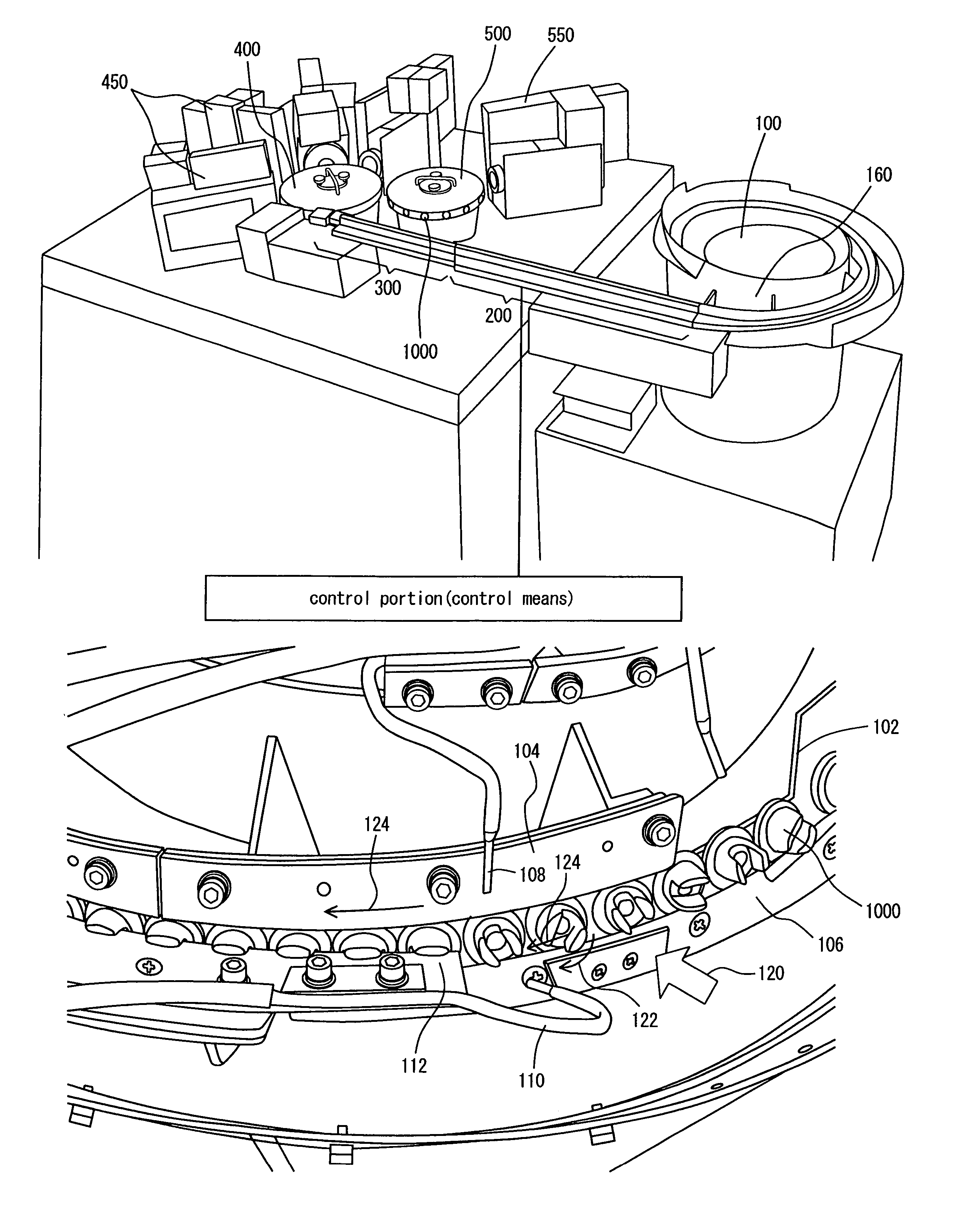
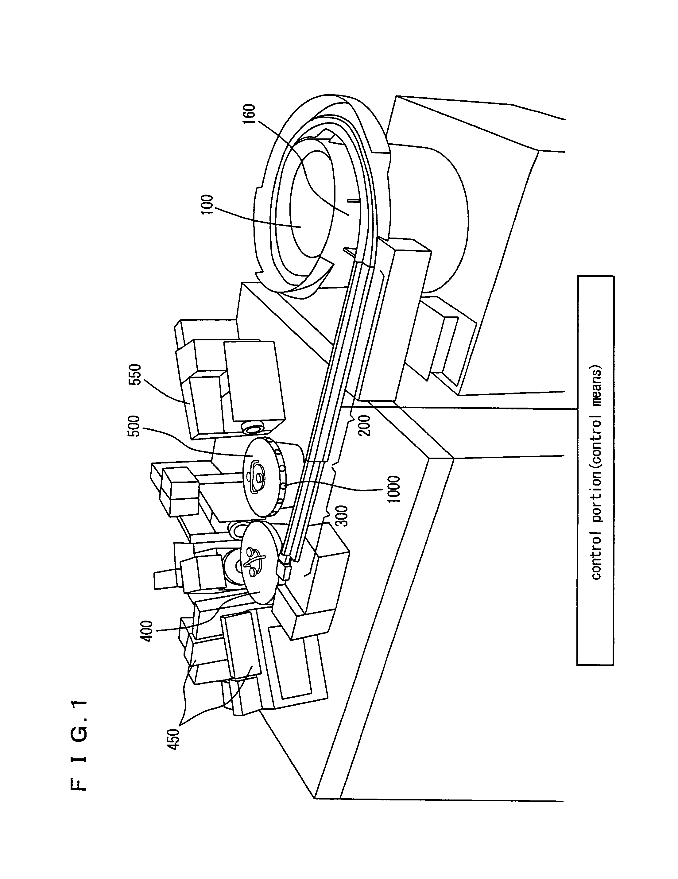
[0043]FIG. 1 is a perspective overall view of the appearance inspecting apparatus in accordance with the present embodiment. As shown in FIG. 1, the appearance inspecting apparatus includes a parts feeder 100 for aligning rubber stoppers 1000 as the objects to be inspected, a linear feeder 200 for conveying rubber stoppers 1000 over linear feeder 200 by applying vibration, in linear direction, to the aligned rubber stoppers 1000, an air conveying portion 300 connected to linear feeder 200 for conveying rubber stoppers 1000 to a first conveying table 400 by blowing compressed air to rubber stoppers 1000 that have been conveyed by linear feeder 200, the first conveying table 400 h...


PUM

PropertyMeasurementUnit
suctionaaaaaaaaaa
speedaaaaaaaaaa
Charge Coupled Deviceaaaaaaaaaa

Abstract

An appearance inspecting apparatus includes a parts feeder aligning rubber stoppers in tandem by torsionally vibrating a bowl having a spiral track formed therein, an air conveying portion conveying the rubber stoppers aligned in tandem by blowing compressed air thereto, first and second conveying tables conveying rubber stoppers by suction-holding a surface not to be inspected of the rubber stoppers, an inspecting portion inspecting a surface to be inspected of the rubber stoppers conveyed by the first and second conveying tables, and a selecting portion sorting out rubber stoppers that are determined to be defective, in accordance with the result of inspection by the inspecting portion. Objects to be inspected having a complicated shape are aligned preliminarily by using a vibration parts feeder, while highly accurate appearance inspection is conducted.

Description

TECHNICAL FIELD[0001]The present invention relates to an apparatus for inspecting an appearance of an object and an apparatus for conveying the object used with the appearance inspecting apparatus and, more specifically, to an inspecting apparatus for inspecting an appearance of an object such as a rubber stopper of an injection solution vial, caps, tablets and capsules having a not-entirely-uniform surface to be inspected, and to a conveying apparatus used for the inspecting apparatus.BACKGROUND ART[0002]A rubber stopper of an injection solution vial is put on an opening of the vial containing the injection solution, and peripheral portion of the stopper is fixed by a clamp. When the injection solution in the vial is to be introduced to a syringe, a syringe needle is put into the center of the rubber stopper.[0003]In this manner, the rubber stopper for an injection vial comes to be in direct contact with the syringe needle. Therefore, it is necessary to inspect the appearance of th...

Claims


Application Information

Patent Timeline
Patent Type & Authority Patents(United States)
IPC IPC(8): B65G53/40B65G47/14B65G47/52B65G47/80B65G47/84B65G51/02B67B1/00
CPCB65G47/1421B65G47/525B65G47/848B67B1/005Y10S209/906
Inventor MINAMI, MITSUHIROTSUTSUMI, KOJIMAKINO, HIROKIOITA, NORIO
Owner DAIICHI JITSUGYO VISWILL
Why Eureka
Try Eureka