Eureka AIR delivers breakthrough ideas for toughest innovation challenges, trusted by R&D personnel around the world.

Control apparatus and control method for hybrid vehicle

a control apparatus and hybrid technology, applied in the direction of gear control, dynamo-electric gear control, instruments, etc., can solve the problem that the second motor/generator may not be able to provide the required output, and achieve the effect of suppressing the increase of the size of the motor

Active Publication Date: 2009-06-23
TOYOTA JIDOSHA KK
View PDF18 Cites 12 Cited by
  • Summary
  • Abstract
  • Description
  • Claims
  • Application Information

AI Technical Summary

Benefits of technology

[0008]It is an object of the invention to suppress an increase of size of a motor and to provide required driving force.
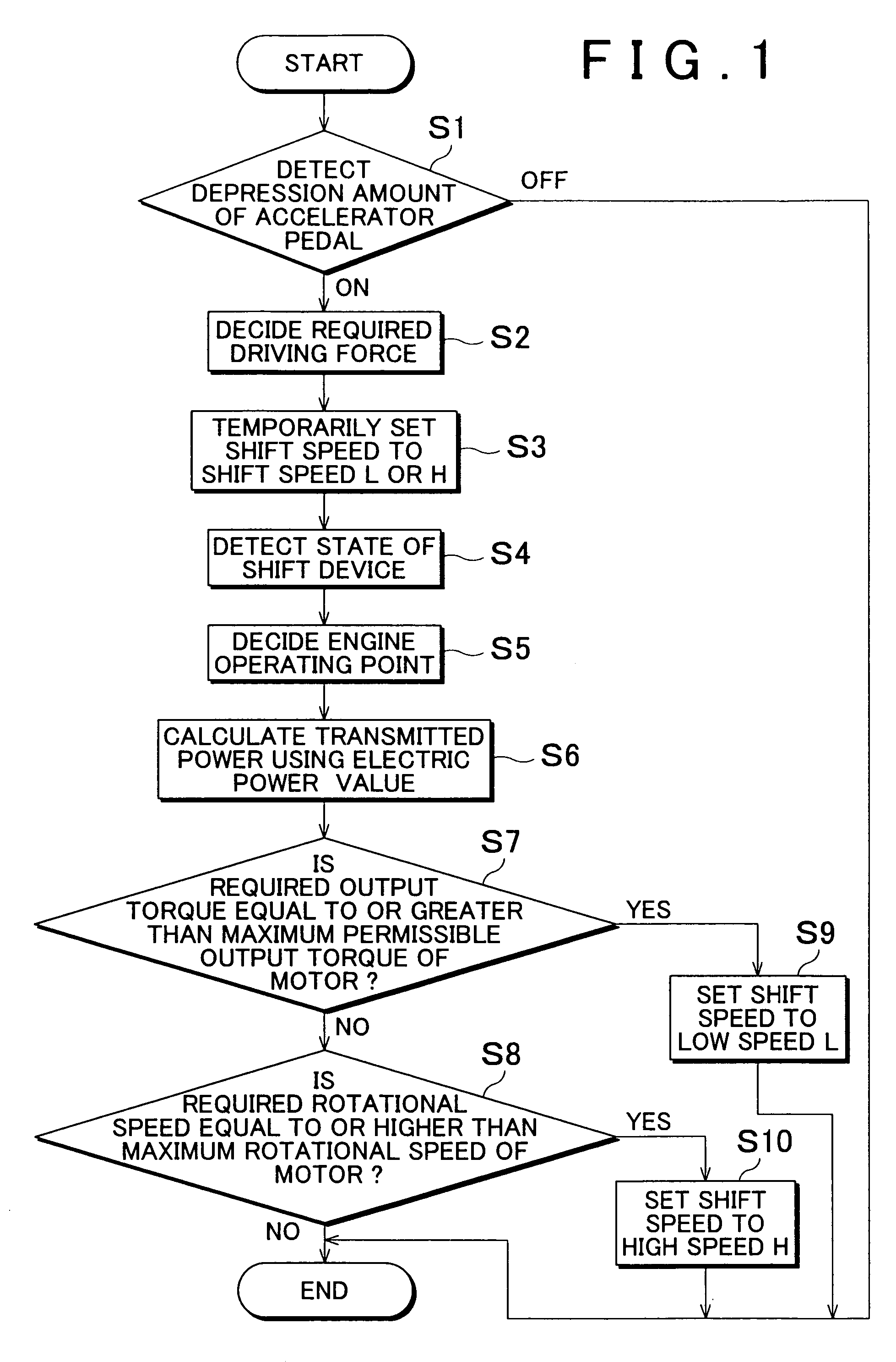
[0012]In the control apparatus according to the second aspect of the invention, the required driving force is detected when a rotational speed of the internal combustion engine is changed, the required torque is calculated based on the detected required driving force, the calculated required torque is compared to the maximum permissible torque of the second driving force source, and the gear ratio of the transmission is changed so as to decrease a rotational speed of the output member when the required torque is greater than the maximum permissible torque. Therefore, since the output torque of the transmission can be increased, it is possible to provide the required torque, and to prevent an increase in size of the second driving force source.
[0014]In the control apparatus according to the third aspect of the invention, the required driving force is detected when the rotational speed of the internal combustion engine is changed, the required rotational speed is calculated based on the detected required driving force, the calculated required rotational speed is compared to the maximum permissible rotational speed of the second driving force source, and the gear ratio of the transmission is changed so as to increase the rotational speed of the output member. Therefore, since the output rotational speed of the transmission can be increased, it is possible to achieve the required rotational speed, and to prevent an increase in size of the second driving force source.

Problems solved by technology

Otherwise, the second motor / generator may not be able to provide the required output due to a limit of the rotational speed of the second motor / generator.

Method used


Image

  • Control apparatus and control method for hybrid vehicle
  • Control apparatus and control method for hybrid vehicle
  • Control apparatus and control method for hybrid vehicle

Examples


Embodiment Construction

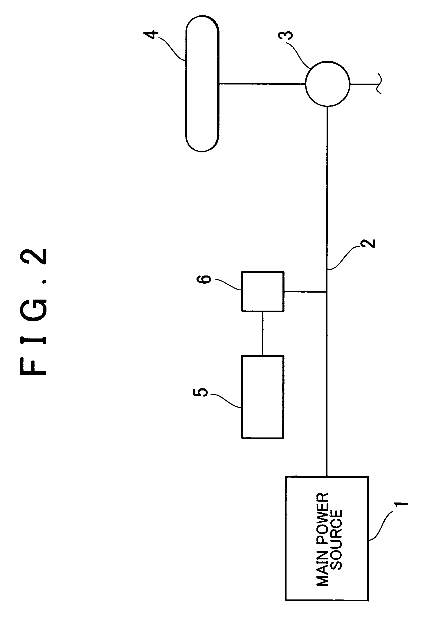
[0023]An embodiment of the invention will be described. As shown in FIG. 2, in a hybrid drive apparatus, torque of a main power source (i.e., a first power source) 1 is transmitted to an output member 2, and the torque is transmitted from the output member 2 to a drive wheel 4 through a differential 3. Meanwhile, an assist power source (i.e., a second power source) 5 is provided. The assist power source 5 can output driving force for running according to power running control, and regenerate energy according to regenerative control. The assist power source 5 is connected to the output member 2 through a transmission 6. Accordingly, torque transmitted between the assist power source 5 and the output member 2 is increased or decreased according to a gear ratio set in the transmission 6.

[0024]The transmission 6 can be configured such that the set gear ratio becomes equal to or greater than “1”. With this configuration, when the assist power source 5 outputs torque at the time of power ...


PUM


Abstract

A control method for a hybrid vehicle which includes an engine, a first motor / generator, a second motor / generator, and a manual changing device that changes a driven state of an output member of the engine that depends on a driving state of the engine and a driving state of the second motor / generator, includes the steps of detecting required driving force of the vehicle; detecting required output torque of the second motor / generator based on the required driving force when a change in a rotational speed of the engine is detected; comparing the detected required torque to the maximum permissible torque of the second motor / generator, and increasing a gear ratio when it is determined that the required output torque is greater than the maximum permissible torque.

Description

INCORPORATION BY REFERENCE[0001]The disclosure of Japanese Patent Application No. 2004-071001 filed on Mar. 12, 2004, including the specification, drawings and abstract is incorporated herein by reference in its entirety.BACKGROUND OF THE INVENTION[0002]1. Field of the Invention[0003]The invention relates to a control apparatus and a control method for a hybrid vehicle including plural driving sources.[0004]2. Description of the Related Art[0005]As a hybrid vehicle, for example, a vehicle which includes a motor or motor / generator as a power source in addition to an internal combustion engine is known. In this example of the hybrid vehicle, an engine rotational speed is controlled by the motor or the motor / generator connected to a planetary gear mechanism so that the internal combustion engine is operated at an optimal operating point, using a differential effect of the planetary gear mechanism. Also, at the time of acceleration, excess or deficiency of driving force or driving force...

Claims


Application Information

Patent Timeline
Patent Type & Authority Patents(United States)
IPC IPC(8): H02P17/00B60K1/02G06F17/00G06F7/00B60W20/00B60K6/445B60K6/54B60K6/547B60K17/04B60L50/16B60W10/06B60W10/10F02D29/00F02D29/02F16H59/16F16H61/00F16H61/02F16H61/68F16H61/684F16H61/686F16H63/50
CPCB60W10/08B60W10/115B60L2240/423B60W20/00B60W2540/10B60W2710/083Y10T477/333F16H2037/0873F16H2061/6603Y02T10/642Y10S903/945Y10T477/33F16H61/0213Y02T10/64B60W20/30B60W10/06B60W10/11
Inventor SUZUKI, YOSHITAKAENDO, HIROATSU
Owner TOYOTA JIDOSHA KK
Why Eureka
Eureka Blog
Learn More