
System and method for reducing ringing artifacts in images

a technology of ringing noise and artifacts, applied in the field of digital signal processing, can solve the problems of blurring in the entire decompressed image, methods that are not effective for ringing noise, and visual artifacts such as blocking noise and ringing noise, and achieve the effect of reducing artifacts in the input imag

Inactive Publication Date: 2009-06-23
MITSUBISHI ELECTRIC RES LAB INC
View PDF12 Cites 17 Cited by
  • Summary
  • Abstract
  • Description
  • Claims
  • Application Information

AI Technical Summary

Benefits of technology

The patent describes a method for reducing artifacts in an image by creating a variance image from the input image and assigning each block of pixels a specific classification based on the variance image. A fuzzy filter is then applied to each pixel in the edge blocks. The technical effect of this method is to improve the quality of the image by reducing the amount of noise and other distortions.

Problems solved by technology

Visual artifacts, such as blocking noise and ringing noise, occur in decompressed images due to the underlying block-based coding, coarse quantization, and coefficient truncation.
Most of the prior art methods deal only with removing blocking noise.
Those methods are not effective for ringing noise.
Some methods, such as the wavelet-based methods, can suppress ringing, but cause blurring in the entire decompressed image.
Those methods do not consider the underlying content of the image, as a whole.
Therefore, those filters either smooth the image excessively to eliminate the artifacts, which causes blurring, or cannot reduce the artifacts sufficiently when minimal smoothing is applied.
Another major problem of those methods is the computational complexity.
The computational cost cannot meet the requirements of real-time processing.
Similar to the wavelet-based method, DCT-domain method also has high computational complexity.
Such high complexity is also impractical for real-time processing.
The computational cost for the iterative method is even higher than that of the above two methods.

Method used


Image

  • System and method for reducing ringing artifacts in images
  • System and method for reducing ringing artifacts in images
  • System and method for reducing ringing artifacts in images

Examples


Embodiment Construction

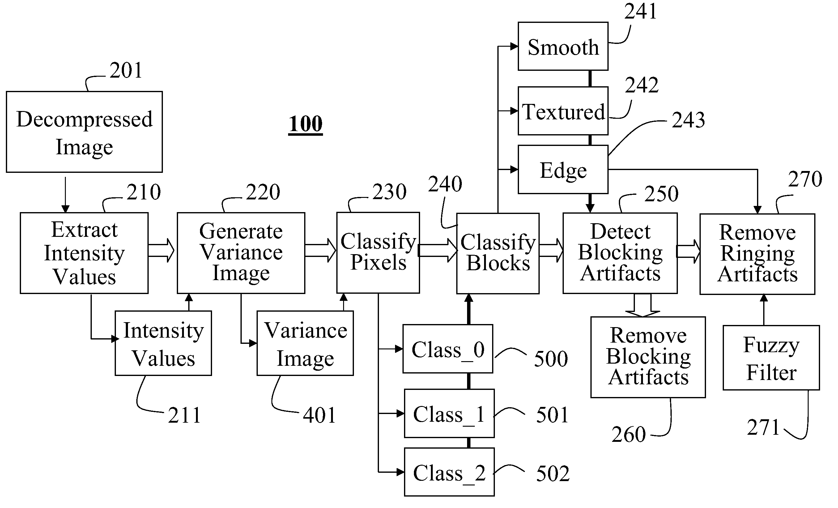
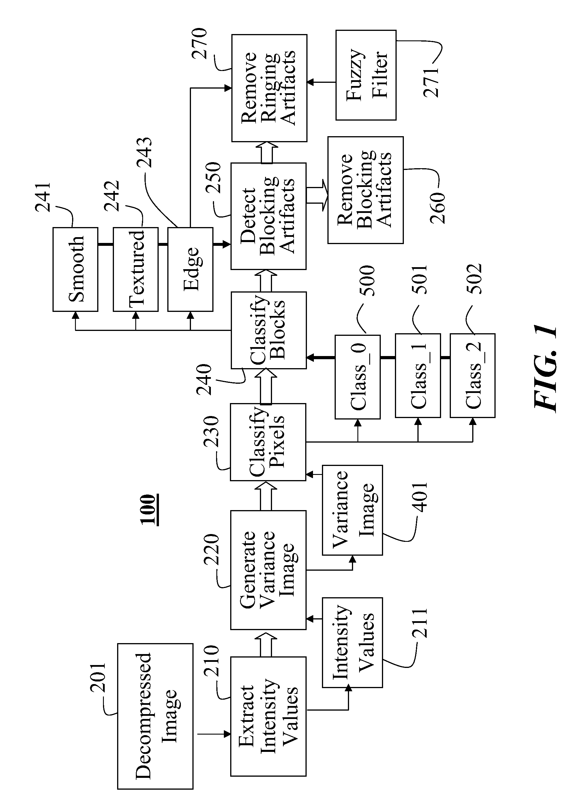
[0025]FIG. 1 shows the system and method 100 according to the invention. This system is independent of any image or video decoder. The system does not rely on any coding parameters embedded in a compressed image or video. The emphasis of our method is on local features in an image. The method according to the invention extracts local features, which are then classified. The classified features can then be used to filter selectively and adaptively the pixels, if the images is a decompressed image or video.

[0026]The input is a decompressed image 201. The method works for any image format, e.g., YUV or RGB. It should be understood that the system can handle a sequence of images as in a video. For example, the image 201 can be part of a progressive or interlaced video. It should also be noted that input image can be source image that has never been compressed.

[0027]However, if the input image is a decompressed image derived from a compresses image, and the compressed image was derived f...


PUM


Abstract

A method reduces artifacts in an input image. A variance image is generated from the input image. The input image is partitioned into a plurality of blocks of pixels. A set of classifications is defined. The set of classifications includes smooth, texture, and edge. A particular classification is assigned to each block of pixels of the input image according to the variance image, to generate smooth blocks, texture blocks, and edge blocks. A fuzzy filter is applied to each pixel of only each edge block.

Description

RELATED APPLICATION[0001]This application is a Continuation-in-Part application of U.S. patent application Ser. No. 10 / 703,809, “System and Method for Classifying and Filtering Pixels Field of the Invention,” filed by Kong et al., on Nov. 7th, 2003.FIELD OF THE INVENTION[0002]The invention relates generally to digital signal processing, and more particularly to reducing image and video coding artifacts.BACKGROUND OF THE INVENTION[0003]Many imaging and video applications, such as digital cameras, HDTV broadcast and DVD, use compression techniques. Most image / video coding standards such as JPEG, ITU-T H.26×and MPEG-1 / 2 / 4 use block-based processing for the compression. Visual artifacts, such as blocking noise and ringing noise, occur in decompressed images due to the underlying block-based coding, coarse quantization, and coefficient truncation.[0004]Many post-processing techniques are known for removing the coding artifacts.[0005]Spatial domain methods are described in U.S. Pat. No. 6...

Claims


Application Information

Patent Timeline
Patent Type & Authority Patents(United States)
IPC IPC(8): G06K9/40G06K9/36G06K9/56G06T5/20G06K9/00G06T5/00H04N1/41H04N5/21H04N7/24H04N7/26H04N7/50
CPCG06T7/0081G06T7/0087H04N19/176H04N19/61H04N19/117H04N19/14H04N19/86G06T2207/20012G06T2207/20021G06T7/11G06T7/143
Inventor KONG, HAO-SONGVETRO, ANTHONYNIE, YAOBARNER, KENNETH EUGEN
Owner MITSUBISHI ELECTRIC RES LAB INC
Learn More