
Transmitter and receiver

Inactive Publication Date: 2009-06-23
TOA CORP
View PDF29 Cites 0 Cited by
  • Summary
  • Abstract
  • Description
  • Claims
  • Application Information

AI Technical Summary

Benefits of technology

[0021]With this arrangement, a coded signal with a lower error rate is first selected from a plurality of coded signals, and blocks which are judged not to contain error are outputted as they are. On

Problems solved by technology

If the count is odd, the data is judged to contain error.
If the number of bits to be checked for error is large, for example, if the entirety of one digital signal is to be checked for

Method used


Image

  • Transmitter and receiver
  • Transmitter and receiver
  • Transmitter and receiver

Examples


Embodiment Construction

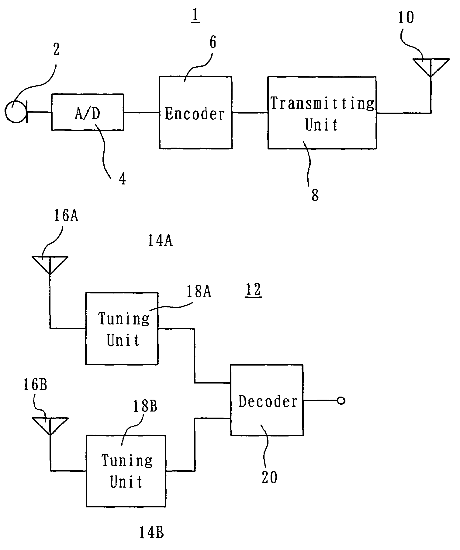
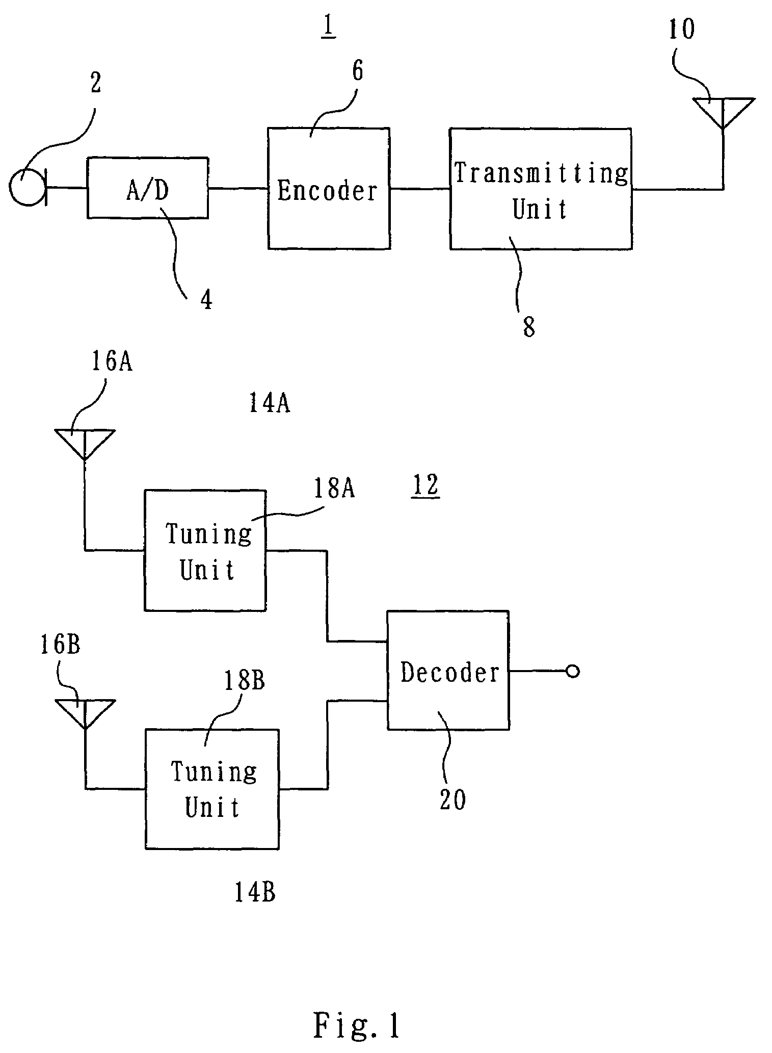
[0030]As shown in FIG. 1, a transmitter 1 according to an embodiment of the present invention includes an analog input signal source, e.g. a microphone 2. An audio signal picked up by the microphone 2 is applied to an A / D converter 4. The A / D converter 4 samples the audio signal at a predetermined sampling frequency and converts it into plural-bit, e.g. 16-bit, digital audio signals. The digital audio signals occur at intervals of the reciprocal of the sampling frequency. These digital audio signals are applied successively to an encoder 6 where they are converted to coded signals. Practically, the encoder 6 assembles a given number of such coded signals to form a frame. The frame configuration does not relate directly to the subject of the present invention, and, therefore, the following description of the invention is given, assuming that the coded signals are outputted from the encoder 6. The coded signals are coupled to a transmitting unit 8. A carrier is digitally modulated wit...


PUM


Abstract

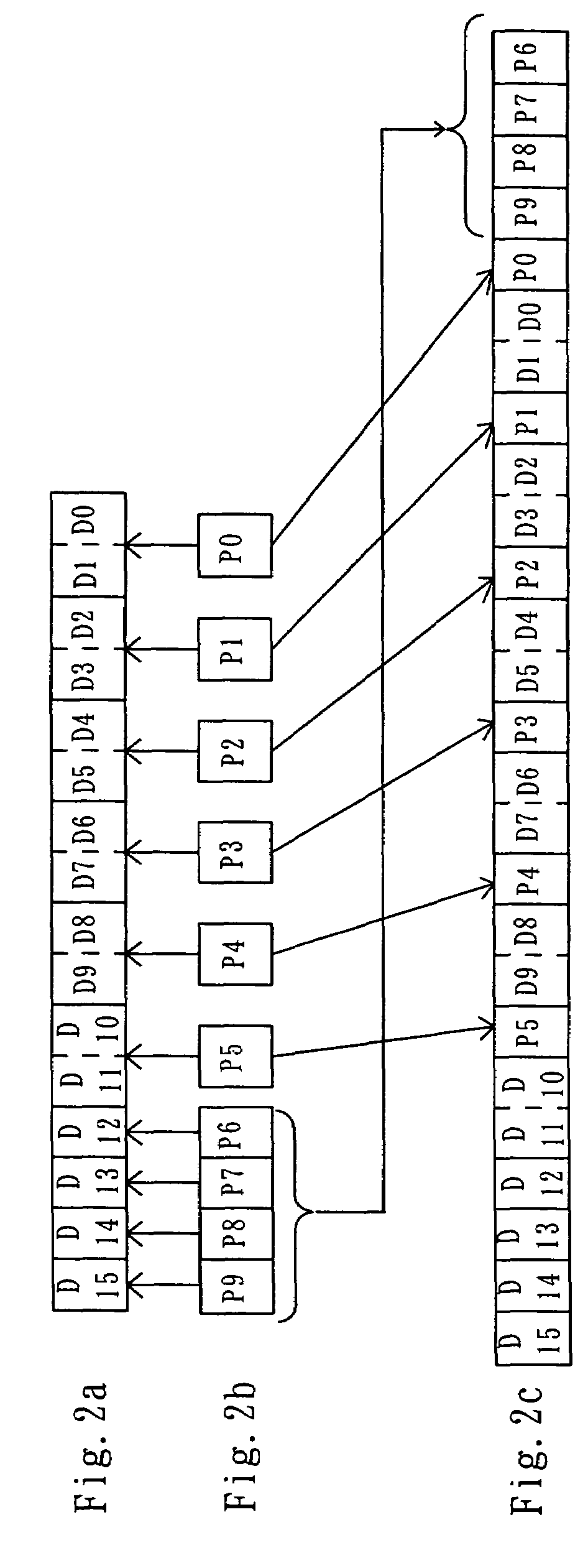
A transmitter (1) converts an input signal from a microphone (2) into a plural-bit digital signal by means of an A/D converter (4) at predetermined time intervals. An encoder (6) divides the digital signal into plural blocks and adds a parity bit to each block to thereby form a coded signal. A transmitting unit (8) modulates a carrier with the coded signal and transmits the modulated carrier through an antenna (10). A receiver (12) includes two tuning units (18A, 18B). Corresponding coded signals outputted from the tuning units (18A, 18B) are inputted to a decoder (20). The decoder (20) makes a parity check on respective blocks of the corresponding coded signals and selects and outputs an error-free one of the corresponding blocks of the corresponding coded signals.

Description

TECHNICAL FIELD[0001]The present invention relates to a transmitter and a receiver and, more particularly, to a digital transmitter and a digital receiver which are provided with measures against transmission error.BACKGROUND[0002]In a digital wireless transmission and reception system, a transmitter transmits a modulated signal comprising a carrier modulated with digital data having “1” or “0” level, while a receiver receives the modulated signal and recovers the digital data from the received signal. Being affected by noise or the like in the radio transmission path between the transmitter and the receiver, it may occur that the “1” or “0” level data cannot properly be recovered to have “1” or “0” level.[0003]One technique for examining whether or not there is any such error is the RSSI system. According to this system, the reception level is examined at a receiver to find out portions of digital data which may contain error. Another technique is to add, at a transmitter, an error...

Claims


Application Information

Patent Timeline
IPC IPC(8): H03K9/00H04L1/00
CPCH04L1/0001H04L1/0045H04L1/007H04L1/06H04L1/20
Inventor SHIBUYA, TAKAKOTANAKA, TOMOHISA
Owner TOA CORP
Learn More