
Reflective type liquid crystal display device and fabrication method thereof

a liquid crystal display and reflector technology, applied in optics, instruments, electrical devices, etc., can solve problems such as limitation, and achieve the effect of enhancing resolution

Active Publication Date: 2009-06-16
E INK CORPORATION
View PDF5 Cites 251 Cited by
  • Summary
  • Abstract
  • Description
  • Claims
  • Application Information

AI Technical Summary

Benefits of technology

[0042]An advantage of the present invention is to provide a reflective type liquid crystal display device and fabricating method thereof, by which resolution is enhanced in a manner of representing two colors from one sub-pixel.
[0043]Additional advantages and features of the invention will be set forth in part in the description which follows and in part will become apparent to those having ordinary skill in the art upon examination of the following or may be learned from practice of the invention. The other advantages of the invention may be realized and attained by the structure particularly pointed out in the written description and claims hereof as well as the appended drawings.
[0044]To achieve these and other advantages and in accordance with the purpose of the invention, as embodied and broadly described herein, a reflective type liquid crystal display device according to the present invention includes a first substrate having a plurality of thin film transistors and a plurality of pixel electrodes within a plurality of sub-pixels defined by a plurality of gate and data lines perpendicularly crossing with each other, respectively, a second substrate assembled to the first substrate to confront, a liquid crystal layer between the first and second substrates, a third substrate assembled to the first substrate to confront, a plurality of reflective electrodes on the third substrate to correspond to a plurality of the sub-pixels, respectively, and a color filter layer having a plurality of electrophoretic bodies on a plurality of the reflective electrodes wherein each of the electrophoretic bodies is micro-encapsulated with ionic pigment particles.
[0045]In another aspect of the present invention, a method of fabricating a reflective type liquid crystal display device includes the steps of forming a plurality of gate and data line on a first substrate to define a plurality of sub-pixels, forming a plurality of thin film transistors at a plurality of intersections between a plurality of the gate and data lines, forming a plurality of pixel electrodes connected to a plurality of the thin film transistors, respectively, assembling a second substrate to the first substrate to confront, forming a liquid crystal layer between the first and second substrates, forming a plurality of reflective electrodes on a third substrate, forming a color filter layer on a plurality of electrophoretic bodies, the color filter layer comprising a plurality of electrophoretic bodies wherein each of the electrophoretic bodies is micro-encapsulated with ionic pigment particles, and assembling the third substrate to the first substrate to confront.
[0046]Preferably, each of the electrophoretic bodies is a first electrophoretic body comprising R and G pigment particles, a second electrophoretic body comprising R and B pigment particles, or a third electrophoretic body comprising G and B pigment particles. And, the R and G, R and B, or G and B pigment particles are charged with opposite polarities, respectively.
[0047]Preferably, oppositely polarized pigment particles within each of the electrophoretic bodies migrate in opposite directions, respectively according to a voltage applied to the corresponding reflective electrode.

Problems solved by technology

However, as three sub-pixels construct one pixel, limitation is put on the related art reflective type liquid crystal display device in raising resolution.

Method used


Image

  • Reflective type liquid crystal display device and fabrication method thereof
  • Reflective type liquid crystal display device and fabrication method thereof
  • Reflective type liquid crystal display device and fabrication method thereof

Examples


first embodiment

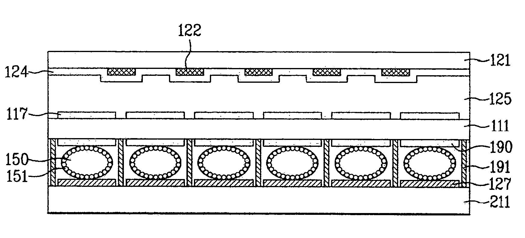
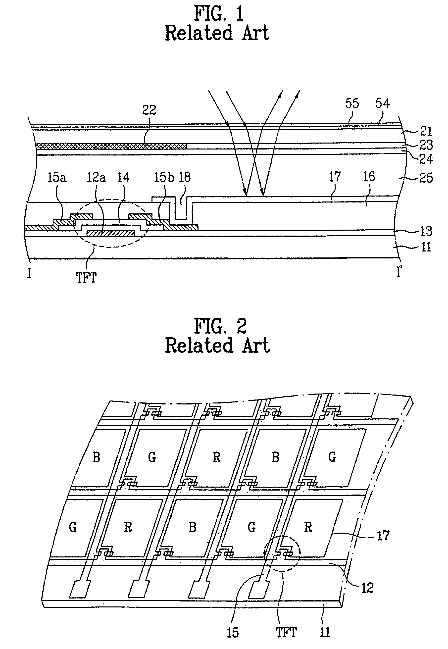
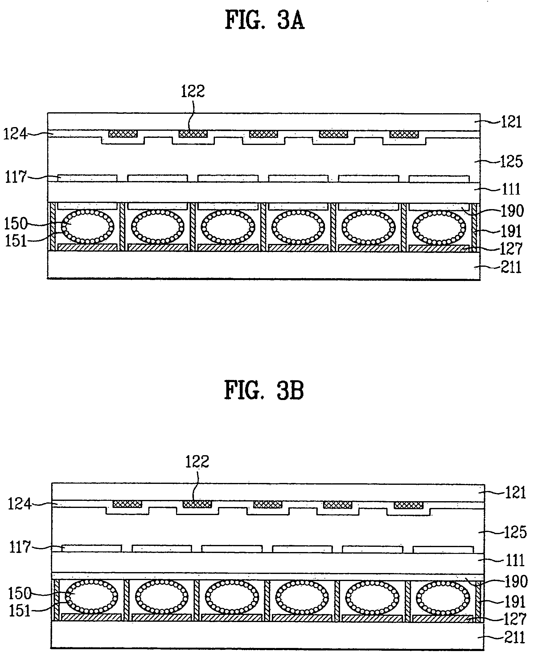
[0066]FIGS. 3A and 3B are cross-sectional diagrams of a reflective type liquid crystal display device according to the present invention; FIG. 4 is a perspective diagram of a reflective type liquid crystal display device according to the present invention; and FIG. 5 is a cross-sectional diagram of a reflective type liquid crystal display device bisected along a cutting line I-I′ in FIG. 4.

[0067]FIG. 6 is a cross-sectional diagram of a reflective type liquid crystal display device according to a second embodiment of the present invention; and FIG. 7 is a cross-sectional diagram of a reflective type liquid crystal display device according to a third embodiment of the present invention.

[0068]Referring to FIGS. 3A and 3B, a reflective type liquid crystal display device according to the present invention includes a thin film array substrate 111 provided with a plurality of lines and thin film transistors, a confronting substrate 121 confronting the thin film transistor array substrate 1...

fourth embodiment

[0120]the present invention will now be described in detail with reference to FIGS. 9 to 11B.

[0121]FIG. 9 is a cross-sectional diagram of a reflective type liquid crystal display device representing the color red (R) according to a fourth embodiment of the present invention; FIG. 10 is a cross-sectional diagram of a reflective type liquid crystal display device representing the color blue (B) according to a fourth embodiment of the present invention; and FIGS. 11A and 11B are cross-sectional diagrams of a reflective type liquid crystal display device representing the color green (G) according to a fourth embodiment of the present invention.

[0122]The liquid crystal display device according to the fourth embodiment of the present invention includes a thin film array substrate 511 provided with a plurality of lines and thin film transistors, a confronting substrate 521 confronting the thin film transistor array substrate 511, a liquid crystal layer 525 injected between the thin film tr...


PUM

PropertyMeasurementUnit
diameteraaaaaaaaaa
diameteraaaaaaaaaa
timeaaaaaaaaaa

Abstract

The present invention provides a reflective type liquid crystal display device and fabricating method thereof, by which resolution is enhanced in a manner of representing two colors from one sub-pixel. The present invention includes a first substrate having a plurality of thin film transistors and a plurality of pixel electrodes within a plurality of sub-pixels defined by a plurality of gate and data lines perpendicularly crossing with each other, respectively, a second substrate assembled to the first substrate to confront, a liquid crystal layer between the first and second substrates, a third substrate assembled to the first substrate to confront, a plurality of reflective electrodes on an inside of the third substrate to correspond to a plurality of the sub-pixels, respectively, and a color filter layer having a plurality of electrophoretic bodies on a plurality of the reflective electrodes wherein each of the electrophoretic bodies is micro-encapsulated with ionic pigment particles.

Description

[0001]This application claims the benefit of the Korean Application No. P2003-79818 filed on Nov. 12, 2003, which is hereby incorporated by reference for all purposes as if fully set forth herein.BACKGROUND OF THE INVENTION[0002]1. Field of the Invention[0003]The present invention relates to a liquid crystal display device, and more particularly, to a reflective type liquid crystal display device and fabricating method thereof, by which resolution is enhanced.[0004]2. Discussion of the Related Art[0005]Recently, a liquid crystal display (LCD) device, one of the noticeable flat panel display devices, controls optical anisotropy by applying an electric field to liquid crystals provided with fluidity of liquid and crystalline optical properties. Thus, an LCD includes features such as power consumption less than that of CRT (cathode ray tube), compact size, wide screen, high definition, and the like, and therefore have become very popular.[0006]In the liquid crystal display device, an u...

Claims


Application Information

Patent Timeline
Patent Type & Authority Patents(United States)
IPC IPC(8): G02F1/1335G02F1/133G02F1/136G02F1/167H01L21/00H01L29/786
CPCG02F1/133514G02F1/167G02F2201/16G02F2201/44G02F2203/02
Inventor LEE, JONG HWAEHUR, JAE HONG
Owner E INK CORPORATION
Learn More