
System for assembling, in particular by welding, structures made up of elements of pressed sheet metal, such as motor-vehicle bodies or subassemblies thereof

a technology of pressed sheet metal and system, which is applied in the direction of soldering apparatus, manufacturing tools,auxillary welding devices, etc., can solve the problems of relative complexity of structure, requiring relatively complex operations, and high time-consuming

Inactive Publication Date: 2009-06-16
COMAU SPA
View PDF39 Cites 14 Cited by
  • Summary
  • Abstract
  • Description
  • Claims
  • Application Information

AI Technical Summary

Benefits of technology

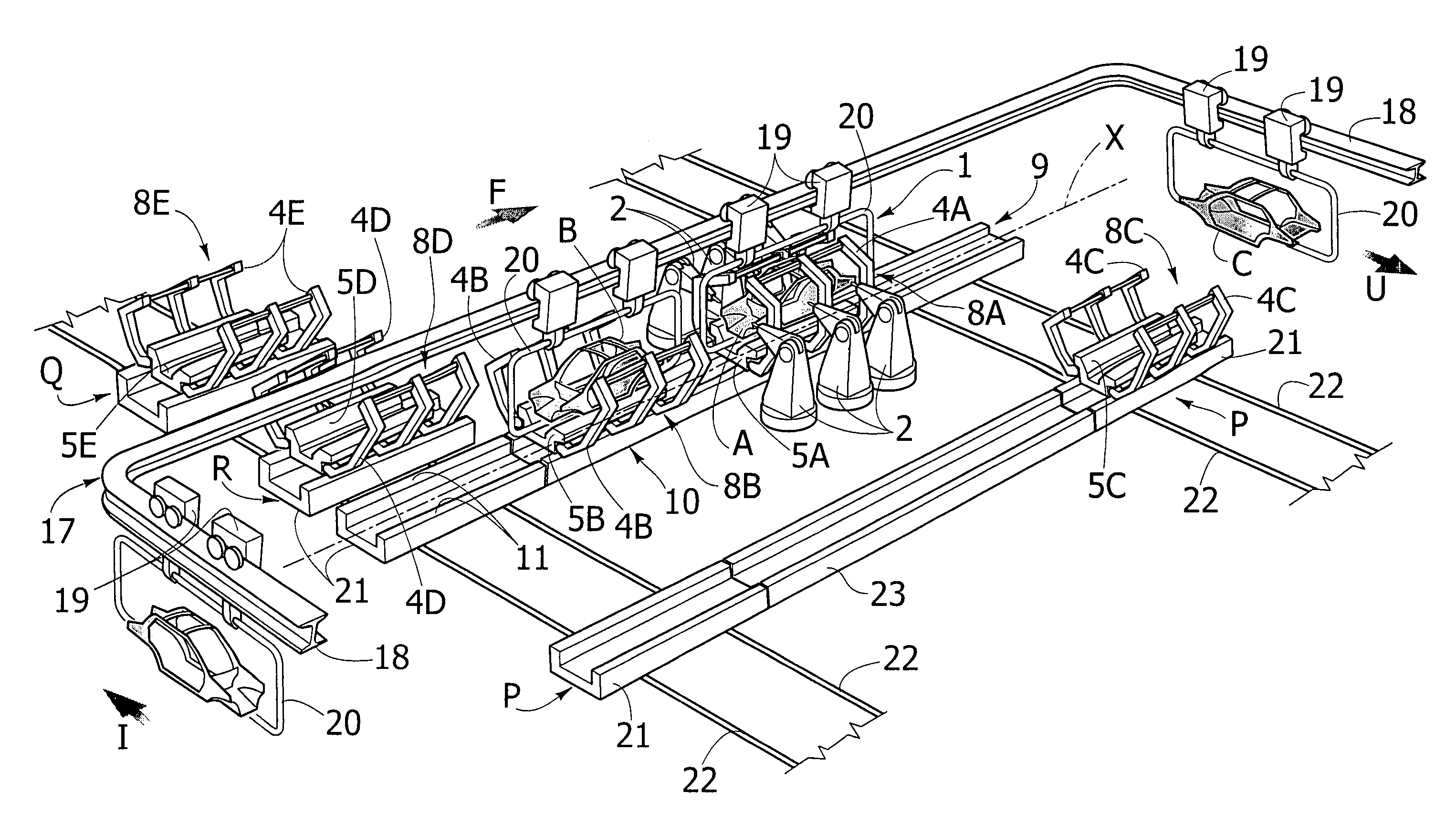
[0015]Thanks to the aforesaid characteristics, a referencing and clamping module can be carried rapidly from the operative position in the assembly station to a waiting position, upstream or downstream of the assembly station, at the end of the operation of assembly. Simultaneously, another module associated to a structure to be assembled can be brought from a waiting position to the operative position in the assembly station.
[0017]In addition, at least one of said transverse conveying lines communicates with a magazine containing referencing and clamping modules corresponding to different types of structure to be assembled. In this way, the system can be adapted to operate on a number, which may even be high, of different types of structure to be assembled.

Problems solved by technology

The known systems of the type referred to above present the drawback of having a relatively complex structure and of requiring operations that are relatively complicated and expensive in terms of time for replacement of the pair of side frames that are in the operative position inside the assembly station.

Method used


Image

  • System for assembling, in particular by welding, structures made up of elements of pressed sheet metal, such as motor-vehicle bodies or subassemblies thereof
  • System for assembling, in particular by welding, structures made up of elements of pressed sheet metal, such as motor-vehicle bodies or subassemblies thereof
  • System for assembling, in particular by welding, structures made up of elements of pressed sheet metal, such as motor-vehicle bodies or subassemblies thereof

Examples


Embodiment Construction

[0023]With reference to the drawings, the reference number 1 designates as a whole an assembly station for assembling, by welding, structures made of pressed sheet metal, in particular motor-vehicle bodies or subassemblies thereof. In the typical case, the station 1 is a framing station, designed for making a sufficient number of welds to bestow a stable geometry upon the body. Provided in a position corresponding to the assembly station 1 are welding robots 2, of any known type, programmed for making a predetermined number of electrical-welding spots on the body that is in the assembly station 1. During execution of the welding operations, the parts of the body are referenced in a precise position, clamped together by means of a plurality of referencing and clamping devices, in themselves of a known type, which are designated as a whole by the reference number 3 in FIG. 3. The system illustrated is designed to operate on different types of motor-vehicle body, for example on differe...


PUM

PropertyMeasurementUnit
distanceaaaaaaaaaa
structuresaaaaaaaaaa
timeaaaaaaaaaa

Abstract

A flexible system for welding motor-vehicle bodies or subassemblies thereof envisages a series of pairs of side frames provided with referencing and clamping devices for keeping in the correct position the structures to be assembled during welding. For each different type of body to be assembled a different pair of side frames is provided, equipped with referencing and clamping devices adapted to the respective type of body. Each pair of side frames is associated to a basic structure, with which it forms a unitary referencing and clamping module. Said modules can be moved through the assembly station to follow one another in the operative welding position, according to the type of body to be welded. The structure to be assembled, or at least part thereof, is fed to the welding station by means of a conveying line that is totally independent and separate from the basic structures of the modules.

Description

BACKGROUND OF THE INVENTION[0001]The present invention relates to systems for assembling, in particular by welding, structures made up of elements of pressed sheet metal, such as motor-vehicle bodies or subassemblies thereof.[0002]In particular, the invention regards an assembly system designed to operate automatically on a plurality of different types of structures to be assembled, for example, on bodies of different models, of the type comprising:[0003]a station for assembly, in particular by welding;[0004]conveying means for carrying at least part of the structures to be assembled to the assembly station and for carrying the assembled structures out of the assembly station; and[0005]a plurality of pairs of side frames provided with position-referencing and clamping means for positioning and clamping the structures to be assembled, the referencing and clamping means provided on the side frames of each pair being adapted to the configuration of a corresponding type of structure to ...

Claims


Application Information

Patent Timeline
Patent Type & Authority Patents(United States)
IPC IPC(8): B23K37/04B25B27/14
CPCB23K37/0426B62D65/18B23K2201/006B23P2700/50Y10T29/53961Y10T29/49968Y10T29/49829B23K2101/006
Inventor MONTI, DENNYBOSSOTTO, PIERO
Owner COMAU SPA
Learn More