
Thin display apparatus

a display device and thin technology, applied in the field of display devices, can solve the problems of poor display quality, large space occupation, thin lcd monitors, etc., and achieve the effect of slim and compact appearance, minimal space for installation, carriage and storag

Inactive Publication Date: 2009-06-09
SAMSUNG ELECTRONICS CO LTD
View PDF20 Cites 11 Cited by
  • Summary
  • Abstract
  • Description
  • Claims
  • Application Information

AI Technical Summary

Benefits of technology

[0015]Accordingly, it is an aspect of the present invention to provide a display apparatus which minimizes a space for installation, carriage and storage, has a slim and compact appearance, and prevents an illusion that a display part of an LCD panel looks relatively small.
[0016]Another aspect of the present invention is to provide a display apparatus which is easily and quickly assembled.

Problems solved by technology

The CRT monitor is widely used because of an economic price and a good display quality thereof, but it occupies a relatively large space because of the bulky size thereof.
The LCD monitor is thin in the thickness thereof, but is expensive in price and poor in display quality, in comparison with the CRT monitor.
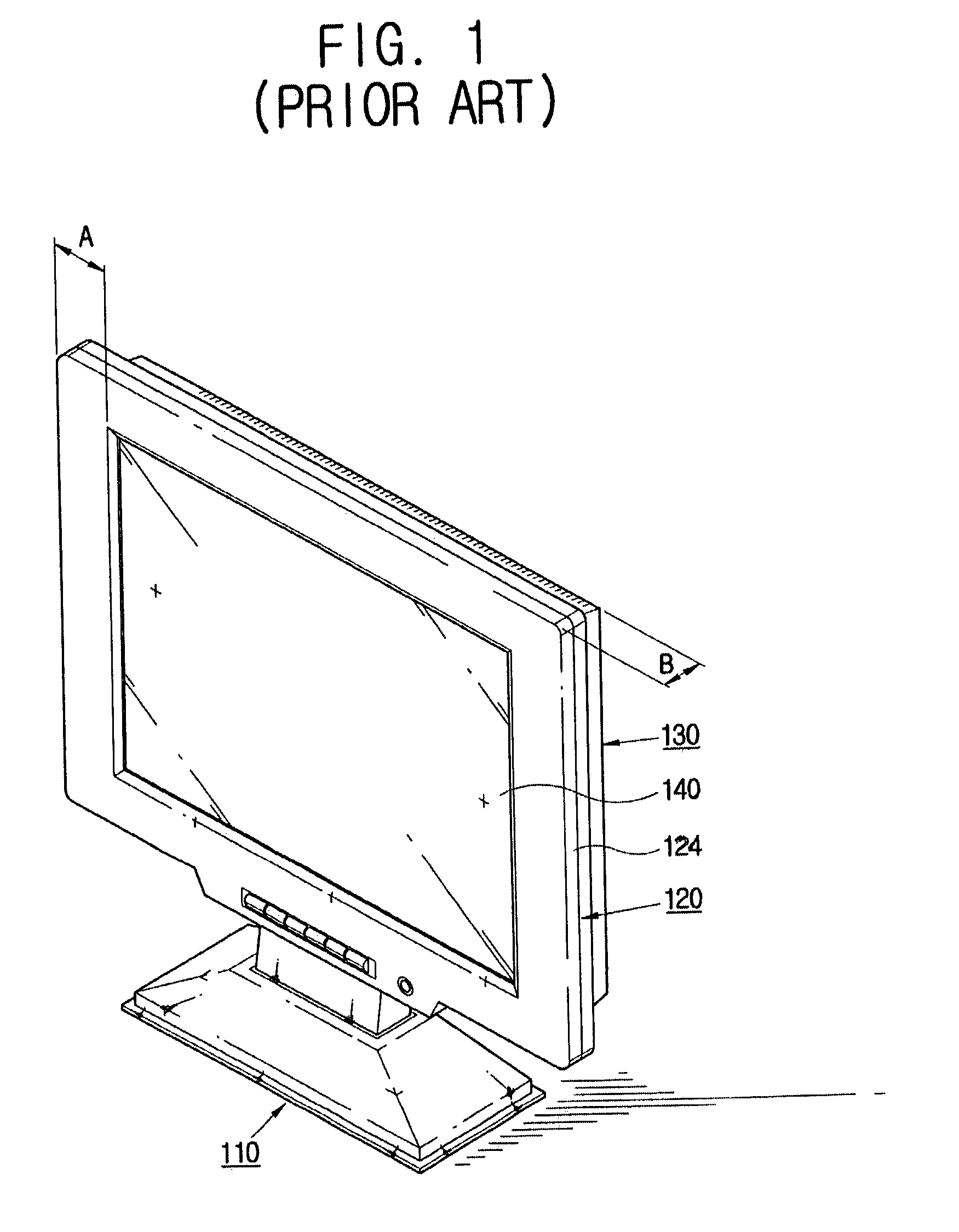
Further, the conventional display apparatus is not adapted for a slim and compact design.
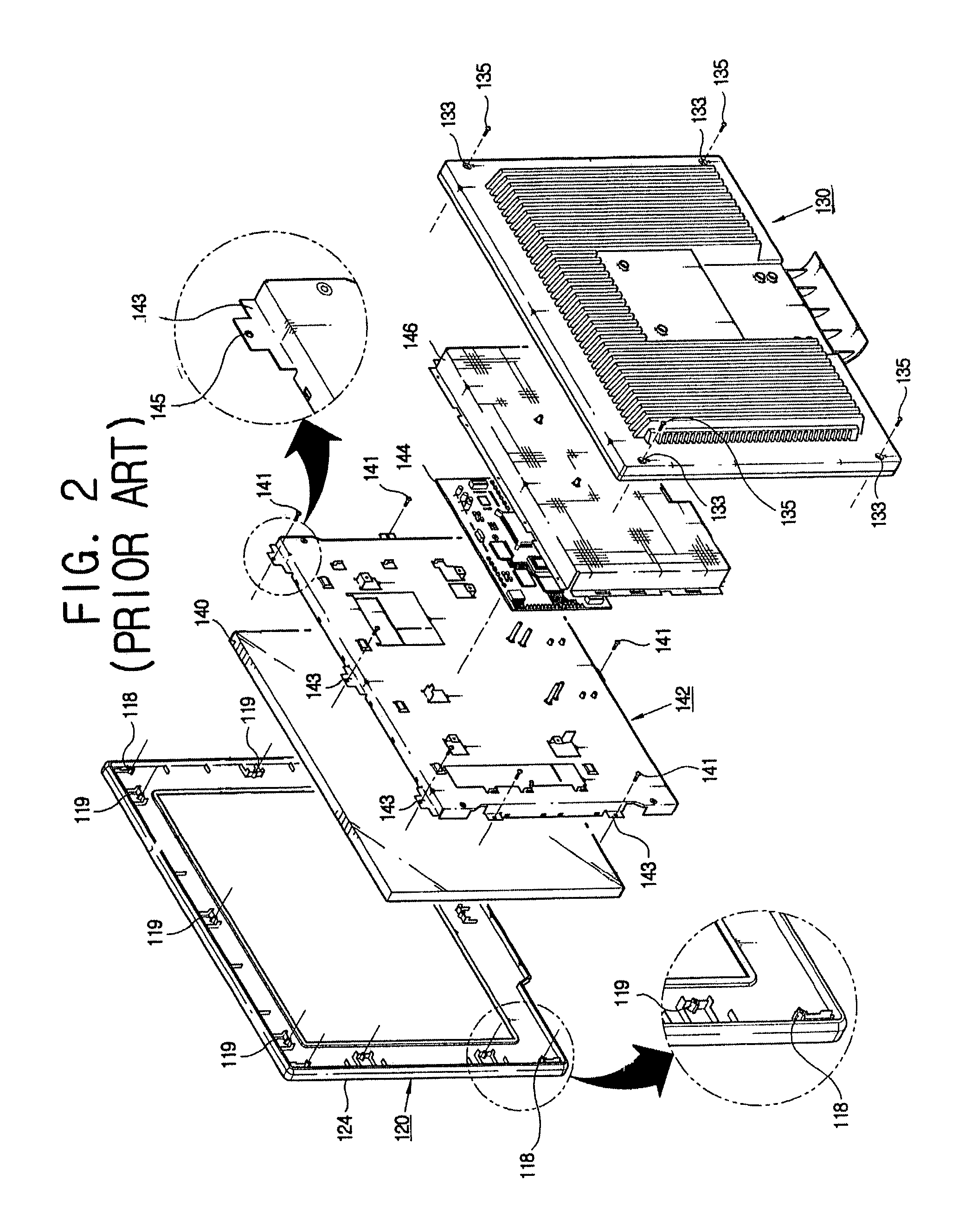
Moreover, because the panel supporting member 142 supporting the LCD panel 140 and the PCB cover 146 covering the PCB assembly 144 are separately provided between the front and rear covers 120 and 130, it is cumbersome and takes a relatively long time to assemble the display apparatus.

Method used


Image

  • Thin display apparatus
  • Thin display apparatus
  • Thin display apparatus

Examples


Embodiment Construction

[0030]Reference will now be made in detail to the present preferred embodiments of the present invention, examples of which are illustrated in the accompanying drawings, wherein like reference numerals refer to the like elements throughout. The embodiments are described below in order to explain the present invention by referring to the figures.

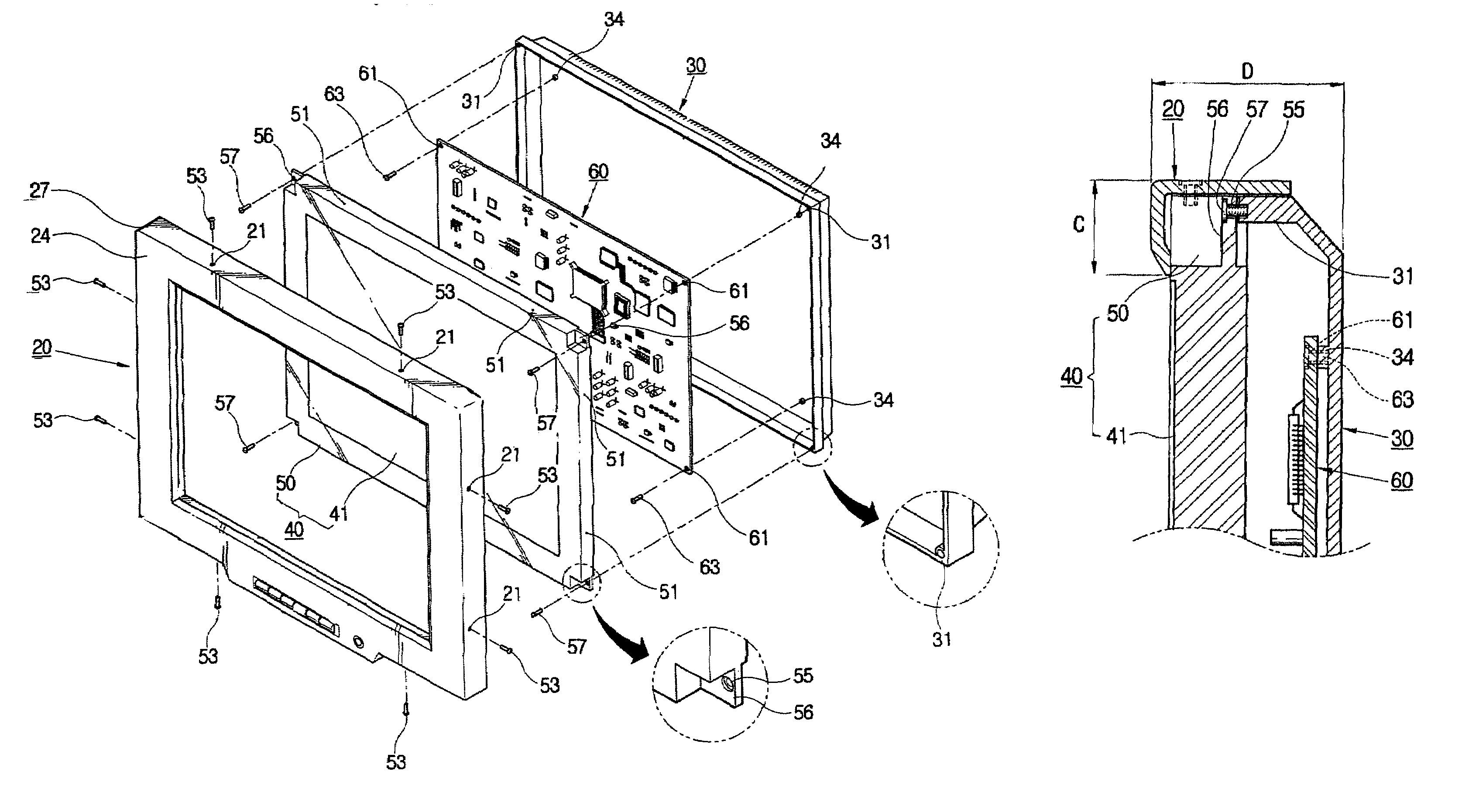
[0031]A display apparatus according to a first embodiment of the present invention, as shown in FIGS. 3 and 4, comprises a base part 10 seated on a predetermined installation surface such as a desk, a wall, etc., an LCD panel 40 having a display part 41 displaying a picture thereon, a PCB assembly 60 placed behind the LCD panel 40 and supplying electric current to the LCD panel 40, a front cover 20 placed in front of the LCD panel 40 and covering edges of the LCD panel 40, and a rear cover 30 combined to the rear of the LCD panel 40 and accommodating the PCB assembly 60.

[0032]The base part 10 is placed in a lower part of the display apparatus...


PUM

PropertyMeasurementUnit
thicknessaaaaaaaaaa
conductiveaaaaaaaaaa
brightnessaaaaaaaaaa

Abstract

A display apparatus includes an LCD panel, a PCB assembly placed behind the LCD panel and supplying electric current to the LCD panel, an LCD frame provided around the LCD panel, a plurality of first combining parts formed on peripheral sides of the LCD frame, and a plurality of second combining parts formed on the plane of the LCD frame. A front cover is placed in front of the LCD panel, covering edges of the LCD panel and is combined to one of the first and second combining parts. A rear cover is placed behind the LCD panel, accommodating the PCB assembly, and is combined to the other one of the first and second combining parts. With this configuration, the present invention provides a display apparatus which minimizes a space for installation, carriage and storage, has a slim and compact appearance, and prevents an illusion that a display part of an LCD panel is relatively small. Further, the present invention provides a display apparatus which need not comprise some components such as a panel supporting member and a PCB cover, thereby being easily and quickly assembled. Furthermore, the present invention provides a display apparatus of which front and rear covers are made of a conductive metal, so that an LCD panel and a PCB assembly are effectively protected from EMI.

Description

CROSS-REFERENCE TO RELATED APPLICATIONS[0001]This application claims the benefit of Korean Patent Application No. 2002-41614, filed Jul. 16, 2002, in the Korean Intellectual Property Office, the disclosure of which is incorporated herein by reference.BACKGROUND OF THE INVENTION[0002]1. Field of the Invention[0003]The present invention relates to a display apparatus, and more particularly, to a display apparatus improved in a combining structure of front and rear covers supporting an LCD (liquid crystal display) panel.[0004]2. Description of the Related Art[0005]A display apparatus collectively refers to monitors for TV sets or computer systems, and includes a CRT (cathode ray tube) monitor, an LCD (liquid crystal display) monitor, etc.[0006]The CRT monitor employs the principle that when various electron beams according to the intensity of picture signals strikes a monochrome or RGB (red, green, blue) fluorescent material coated on a CRT panel, light having different brightness and ...

Claims


Application Information

Patent Timeline
Patent Type & Authority Patents(United States)
IPC IPC(8): G02F1/1333G06F1/16G02F1/13
CPCG02F1/133308G02F2201/46G02F2001/13332G02F2001/133314G02F1/133314G02F1/13332G06F1/16
Inventor KIM, KWEY-HYUN
Owner SAMSUNG ELECTRONICS CO LTD
Learn More