
Zoom lens and image capture apparatus

a zoom lens and image technology, applied in the field of zoom lenses and image capture apparatuses, can solve the problems of out-of-focus image, increased field curvature, and increased difficulty in fulfilling miniaturization or the like, and achieve the effect of high zoom ratio and high image quality

Inactive Publication Date: 2009-06-02
SONY CORP
View PDF12 Cites 7 Cited by
  • Summary
  • Abstract
  • Description
  • Claims
  • Application Information

AI Technical Summary

Benefits of technology

The present invention provides a zoom lens for small-size image capture apparatuses that provides a high image quality and a high zoom ratio while having a small size. The lens includes a first lens group, a second lens group, a third lens group, a fourth lens group, and a fifth lens group, each with at least one aspherical surface. The lens groups are designed to correct the curvature of field and provide focusing while zooming. The invention solves the problem of variation in the curvature of field resulting from changes in object distance, which can cause an out-of-focus image, especially in the periphery of the image. The invention also addresses the issue of miniaturization of the image capture apparatus and the difficulty in achieving both a high zoom ratio and small size.

Problems solved by technology

However, in the zoom lenses for the video cameras in the related art, particularly, along with an attempt to provide a higher zoom ratio, there are following issues.
In addition, this fact is naturally followed by an issue in that the higher an image height is, in other words, the greater a size of imagers such as CCDs (Charge Coupled Devices) is, the greater is an amount of the curvature of field as well.
Such being the case, in regard to a demand for higher pixel density with the increase of the imager size, if variation due to the change in the object distance is to be suppressed, it becomes more difficult to fulfill the miniaturization or the like.
This fact causes the periphery of the image to be out of focus, resulting in an out-of-focus image.
It is unfavorable for capturing an image of a subject whose distance changes greatly, because a manner of out-of-focus in the periphery of the image undergoes a large change as well.

Method used


Image

  • Zoom lens and image capture apparatus
  • Zoom lens and image capture apparatus
  • Zoom lens and image capture apparatus

Examples


first embodiment

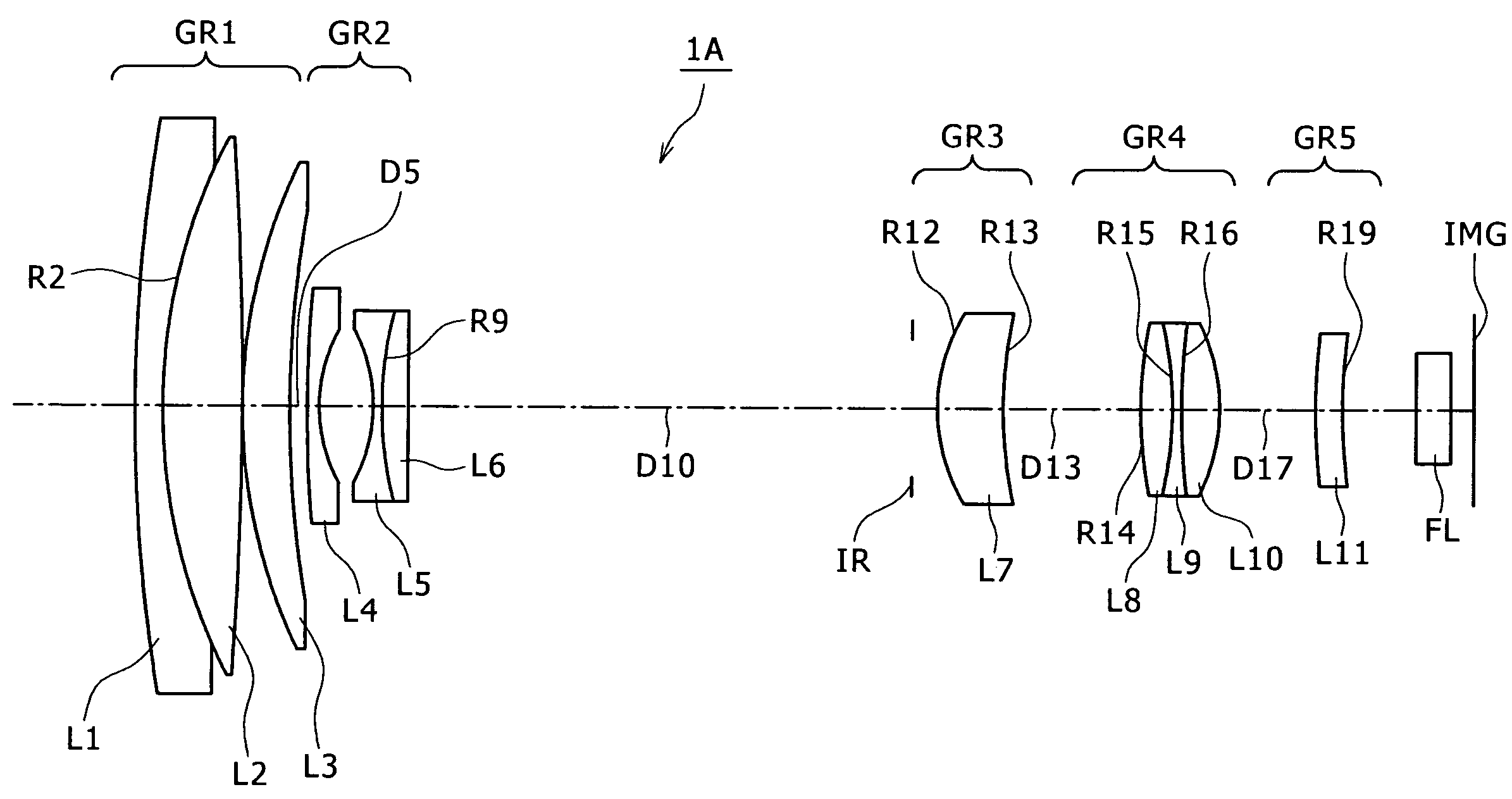
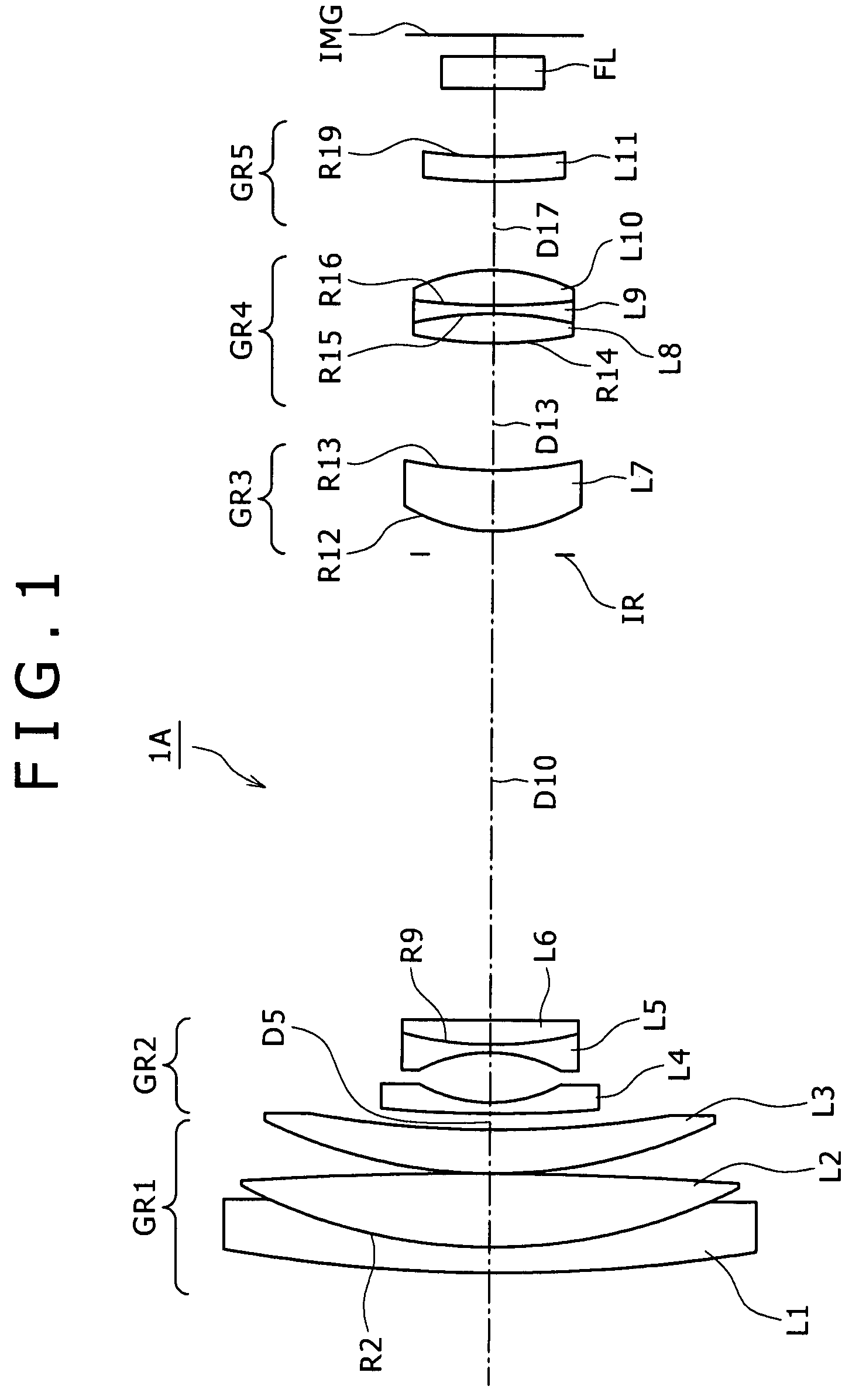
[0063]The zoom lens 1A includes eleven lenses in total, as shown in FIG. 1.

[0064]The first lens group GR1 has the positive refractive power on the whole, and is configured with three lenses L1, L2 and L3. It is noted that with respect to the lenses L1 and L2, a concave surface and a convex surface that are respectively on an image-plane side of the lens L1 and an object side of the lens L2 and have the same radius of curvature are cemented together into a cemented lens having a cemented surface R2.

[0065]The second lens group GR2 has the negative refractive power on the whole, and is configured with three lenses L4, L5 and L6. The second lens group GR2 is movable in position for movement in the direction of the optical axis for providing mainly zooming. It is noted that with respect to the lenses L5 and L6, a concave surface and a convex surface that are respectively on an image-plane side of the lens L5 and an object side of the lens L6 and have the same radius of curvature are cem...

embodiment 1

[0072]A change of a lens position state from the maximum wide-angle state to the maximum telephoto state results in changes of a surface gap D5 between the first lens group GR1 and the second lens group GR2, a surface gap D10 between the second lens group GR2 and the stop IR, a surface gap D13 between the third lens group GR3 and the fourth lens group GR4 and a surface gap D17 between the fourth lens group GR4 and the fifth lens group GR5. Such being the case, a table 2 shows values for each of the surface gaps D5, D10, D13 and D17 at the maximum wide-angle state (f=1.00), the mid-focal length (f=4.84) and the maximum telephoto state (f=23.45) according to the numerical embodiment 1 when the object distance is of infinity. A table 3 shows those when the object distance is of 2 m.

[0073]

TABLE 2FOCAL LENGTH(AT INFINITY)14.84223.451D50.2775.3208.129D108.1563.1130.304D132.1980.9813.192D171.5912.8090.597

[0074]

TABLE 3FOCAL LENGTH(AT 2M)14.84223.451D50.2775.3208.129D108.1563.1130.304D132.19...

second embodiment

[0081]The zoom lens 1B includes eleven lenses in total, as shown in FIG. 9.

[0082]The first lens group GR1 has the positive refractive power on the whole, and is configured with three lenses L1, L2 and L3. It is noted that with respect to the lenses L1 and L2, a concave surface and a convex surface that are respectively on the image-plane side of the lens L1 and the object side of the lens L2 and have the same radius of curvature are cemented together into a cemented lens having a cemented surface R2.

[0083]The second lens group GR2 has the negative refractive power on the whole, and is configured with three lenses L4, L5 and L6. The second lens group GR2 is movable in position for movement in the direction of the optical axis for providing mainly zooming. It is noted that with respect to the lenses L5 and L6, a concave surface and a convex surface that are respectively on the image-plane side of the lens L5 and the object side of the lens L6 and have the same radius of curvature are...


PUM


Abstract

A zoom lens includes in order and from the side of an object, a first lens group having a positive refractive power and fixed in position, a second lens group having a negative refractive power and movable in position for providing mainly zooming, a third lens group having a positive refractive power and fixed in position, a fourth lens group having a positive refractive power and movable in position for performing a focal position correction due to the zooming and for focusing, and a fifth lens group including a single lens fixed in position.Each of the lens groups from the third lens group to the fifth lens group has at least one aspheric surface, and conditional equations (1) and (2) below are satisfied.|f4 / f5|<0.12  (3)0.9<β5<1.2  (4)where f4 is a focal length of the fourth lens group, f5 is a focal length of the fifth lens group, and β5 is a transverse magnification of the fifth lens group.

Description

BACKGROUND OF THE INVENTION[0001]1. Field of the Invention[0002]The present invention relates to a zoom lens and image capture apparatus. More specifically, the present invention relates to a zoom lens that provides a higher performance and a higher zoom ratio while having a small size, as well as to an image capture apparatus equipped with such a zoom lens.[0003]2. Description of Related Art[0004]In recent years, small-size image capture apparatuses such as consumer video cameras and digital video cameras have been wide spread for household use. For the small-size image capture apparatuses of this type, portability is taken into serious consideration. Miniaturization is always desired as well as a higher image quality. For that reason, with respect to image-capturing lenses, particularly zoom lenses respectively mounted in the small-size image capture apparatuses, there is a need for a smaller size as well as enhancement of lens performances. The smaller size may be achieved, for e...

Claims


Application Information

Patent Timeline
Patent Type & Authority Patents(United States)
IPC IPC(8): G02B15/14
CPCG02B15/173G02B15/145129G02B15/145113G02B13/009G02B3/04G02B3/0087G02B3/0062G03B17/12H04N23/55
Inventor TOYODA, KOJINANJO, YUSUKEARITA, SHINICHI
Owner SONY CORP
Learn More