
Field unit for mounting on an actuator

a field unit and actuator technology, applied in the direction of valve housing, hose connection, water supply installation, etc., can solve the problems of inability to mount easily, actuator to operate incorrectly, dirt and moisture can enter the interior of the field unit, etc., to achieve the effect of easy mounting

Active Publication Date: 2009-06-02
SAMSON AG
View PDF4 Cites 0 Cited by
  • Summary
  • Abstract
  • Description
  • Claims
  • Application Information

AI Technical Summary

Benefits of technology

[0012]The invention is based on the task of improving a field unit for mounting on an actuator in such a way that the field unit can be mounted easily on the actuator without the need to deal with any of the previously mentioned disadvantages.
[0013]The invention is based on the realization that faster and easier installation can be guaranteed by reducing the number of procedures required to mount the field unit on the actuator.
[0014]For this purpose, the field unit which is to be mounted on the actuator has a pickup device for registering the position of the actuator. Accordingly, an indicator for conveying the position of the actuator is mounted on a movable element of the actuator, and when the field unit is being mounted on the actuator, the pickup device can be linked with this indicator. According to the invention, the pickup of the field unit is in working connection with a locking element and is held in place by this locking element in a first position—the mounting position. By actuation of the locking element during or after the mounting of the field unit, the pickup is released from the mounting position so that it can be linked with the indicator of the actuator. The manner in which the pickup of the field unit is held in the mounting position according to the invention guarantees that the unit can mounted quickly and easily, because attaching the field unit to the actuator requires merely that the field unit be brought up to the actuator and that the locking element be actuated. Another advantage is that the entire mounting process can be carried out one-handedly. No other manipulations in the intermediate space between the field unit and the actuator are necessary. In addition, thanks to the inventive design, there is no longer any need to make any fine adjustments or to open the field unit.

Problems solved by technology

When a unit is installed in the field, however, considerable difficulties can arise.
Depending on the weather conditions and on the accessibility of the drive unit, the following aspects of the mounting process can be disadvantageous: The simultaneous mounting of the field unit and the connection of the displacement indicator linkage—usually done by introducing a pin into a slot—requires two hands and depends on the exact positioning of the field unit.
This can lead to an incorrect connection of the displacement indicator linkage, which in turn causes the actuator to operate incorrectly.
This leads to the disadvantage that dirt and moisture can intrude into the interior of the field unit.
In addition, the manual positioning of the field unit also means that expensive measures must be taken to design the interior of the unit so that it can be adjusted properly.
Providing a mechanical access hole, for example, and a corresponding opening in the circuit board for the electronic components is associated with high manufacturing costs.
The manual operations which must be performed when mounting the field unit on the actuator, namely, the positioning and adjustment of the components, also present the risk of injury.
Although this does make mounting easier, most of the disadvantages mentioned above, such as the need to open the field unit, the two-handed procedures, etc., remain unaffected.
Although this again makes it easier to install the unit, the disadvantages of two-handed manipulation and of the need to open the field unit, with all the associated design disadvantages, remain unaffected.

Method used


Image

  • Field unit for mounting on an actuator
  • Field unit for mounting on an actuator

Examples


Embodiment Construction

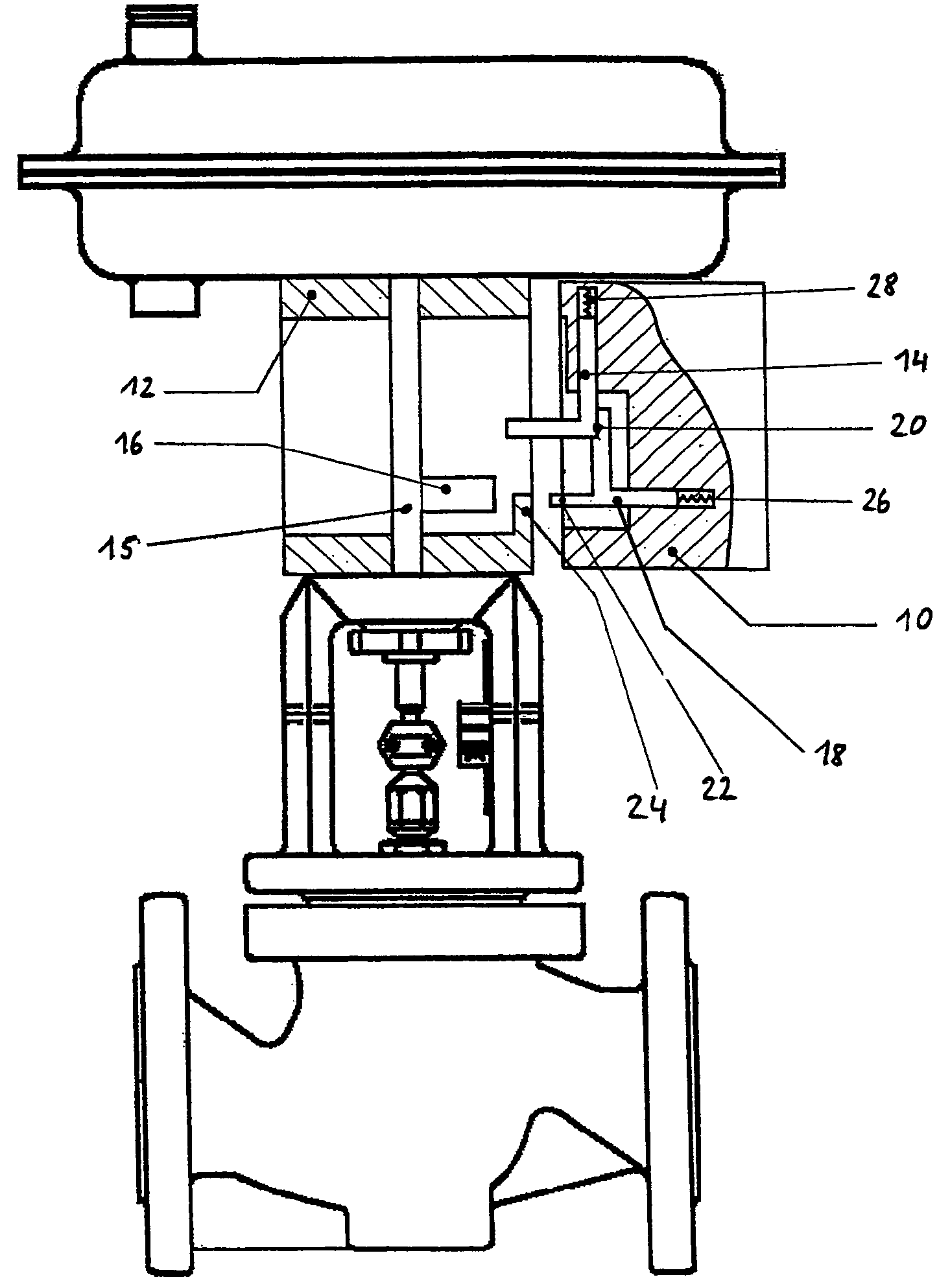
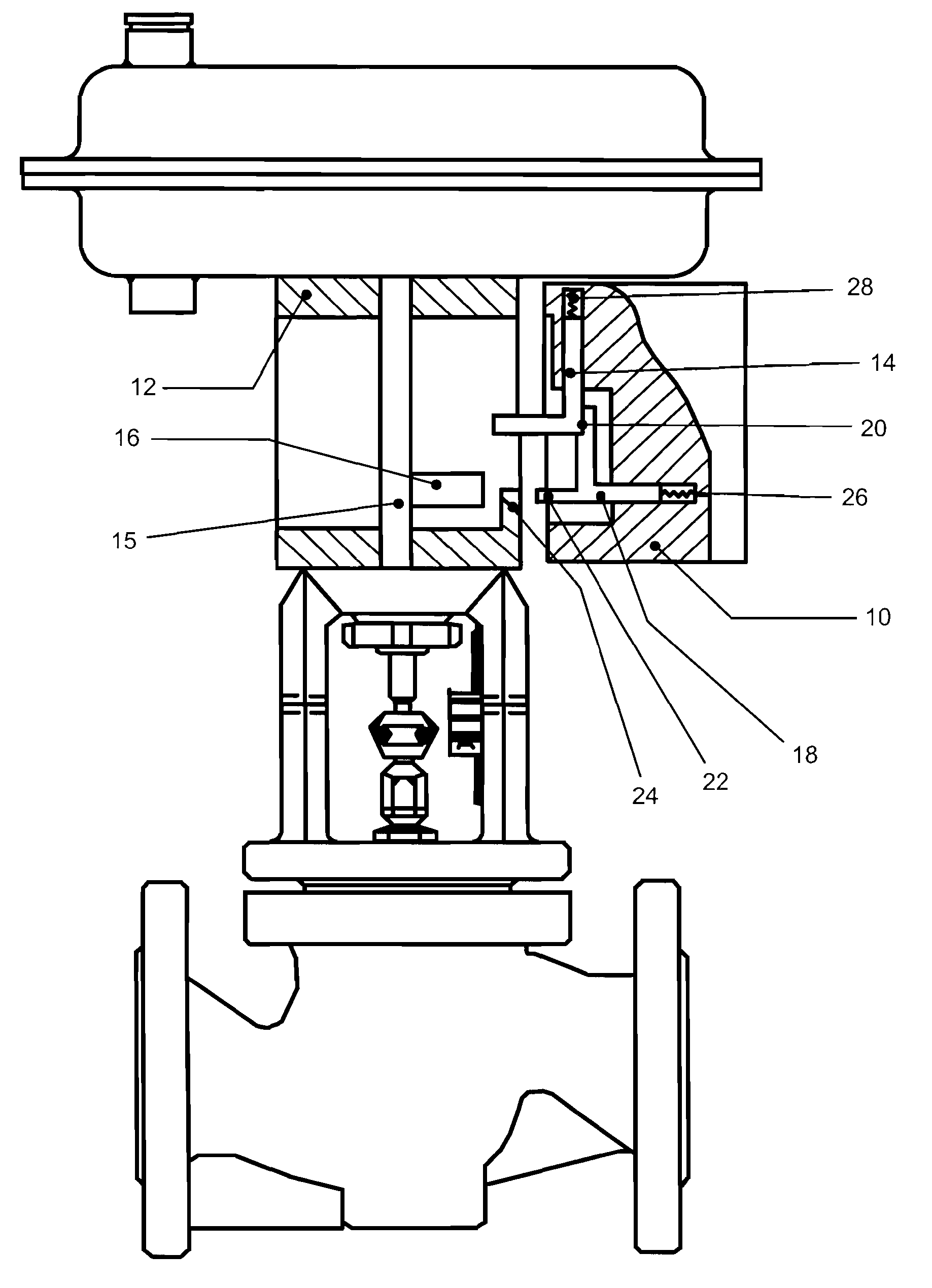
[0036]The drawing FIGURE shows in more-or-less schematic fashion a field unit 10 for mounting on an actuator 12.

[0037]In addition to the electronic components, not shown here for the sake of clarity, the field unit 10 comprises a pickup device 14, which can register the position of the actuator 12.

[0038]So that it can convey its position effectively, the actuator 12 has an indicator 16, mounted on a movable valve rod 15.

[0039]The pickup device 14 of the field unit 10 is in working connection with a locking element 18 and is held in position by the locking element 18 in the position shown, referred to in the following as the “mounting position”. The locking element 18 can hold the pickup device 14 of the field unit 10 only in this one position, namely, in the mounting position illustrated.

[0040]Also characteristic of the illustrated mounting position is that the pickup device 14 of the field unit 10 is situated at an end point of the detection range of the field unit 10.

[0041]So that...


PUM


Abstract

The invention pertains to a field unit (10) for mounting on an actuator (12) with a pickup device (14) in the field unit (10) to register the position of the actuator (12) and with an indicator (16) located correspondingly on a movable element (15) of the actuator (12) to indicate the position of the actuator (12), where, when the field unit (10) is mounted on the actuator (14), the pickup device (14) of the field unit (10) can be linked with the indicator (16) of the actuator (12). The invention is characterized in that the pickup device (14) of the field unit (10) is in working connection with a locking element (18), and in that the pickup device (14) can be held by this locking element (18) in a first position—the mounting position—and can be released from the mounting position by the actuation of the locking element (18).

Description

[0001]This patent application claims priority to German Patent application number 10 2005 003 771.2-55 filed Jan. 27, 2005.FIELD OF THE INVENTION[0002]The invention pertains to a field unit for mounting on an actuator.BACKGROUND OF THE INVENTION[0003]It is known that a field unit such as a positioner, a response synchro, or a limit switch is frequently attached to or installed on an electrical or pneumatic servo / actuator for positioning a valve in accordance with DIN IEC 60534-6.[0004]The mounting of the field unit must encompass essentially two tasks: First, a connection must be established between the field unit and the actuator; second, the linkage—usually mechanical—by which the position of the actuator is conveyed to the field unit must be connected and adjusted.[0005]This procedure does not usually cause any problems when performed at the factory of the manufacturer. When a unit is installed in the field, however, considerable difficulties can arise.[0006]Depending on the weat...

Claims


Application Information

Patent Timeline
IPC IPC(8): F16K37/00
CPCF16K31/126F16K37/0041Y10T137/7043Y10T137/8242Y10T137/8275
Inventor VALENTIN-RUMPEL, FRANK
Owner SAMSON AG
Learn More