
Cable winding conversion device

a conversion device and cable technology, applied in the field of cable, can solve the problems of limited parts where the base member and the cable can be mounted (placed), difficult to place the cable and and difficult to place the base member on the frame and the cable on the frame, etc., to achieve the effect of convenient placement, easy placement and convenient cable placemen

Inactive Publication Date: 2009-06-02
SHIMANO INC
View PDF15 Cites 4 Cited by
  • Summary
  • Abstract
  • Description
  • Claims
  • Application Information

AI Technical Summary

Benefits of technology

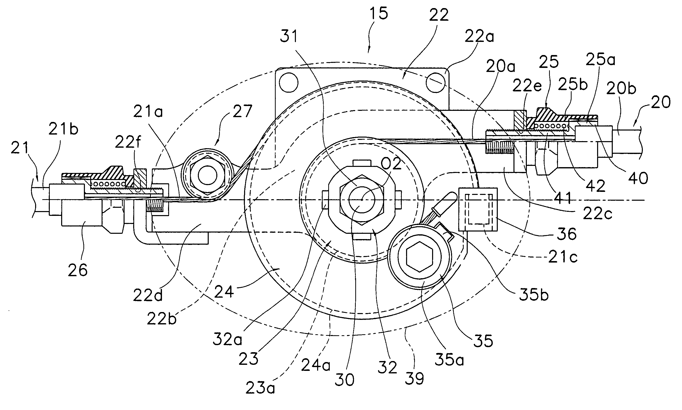
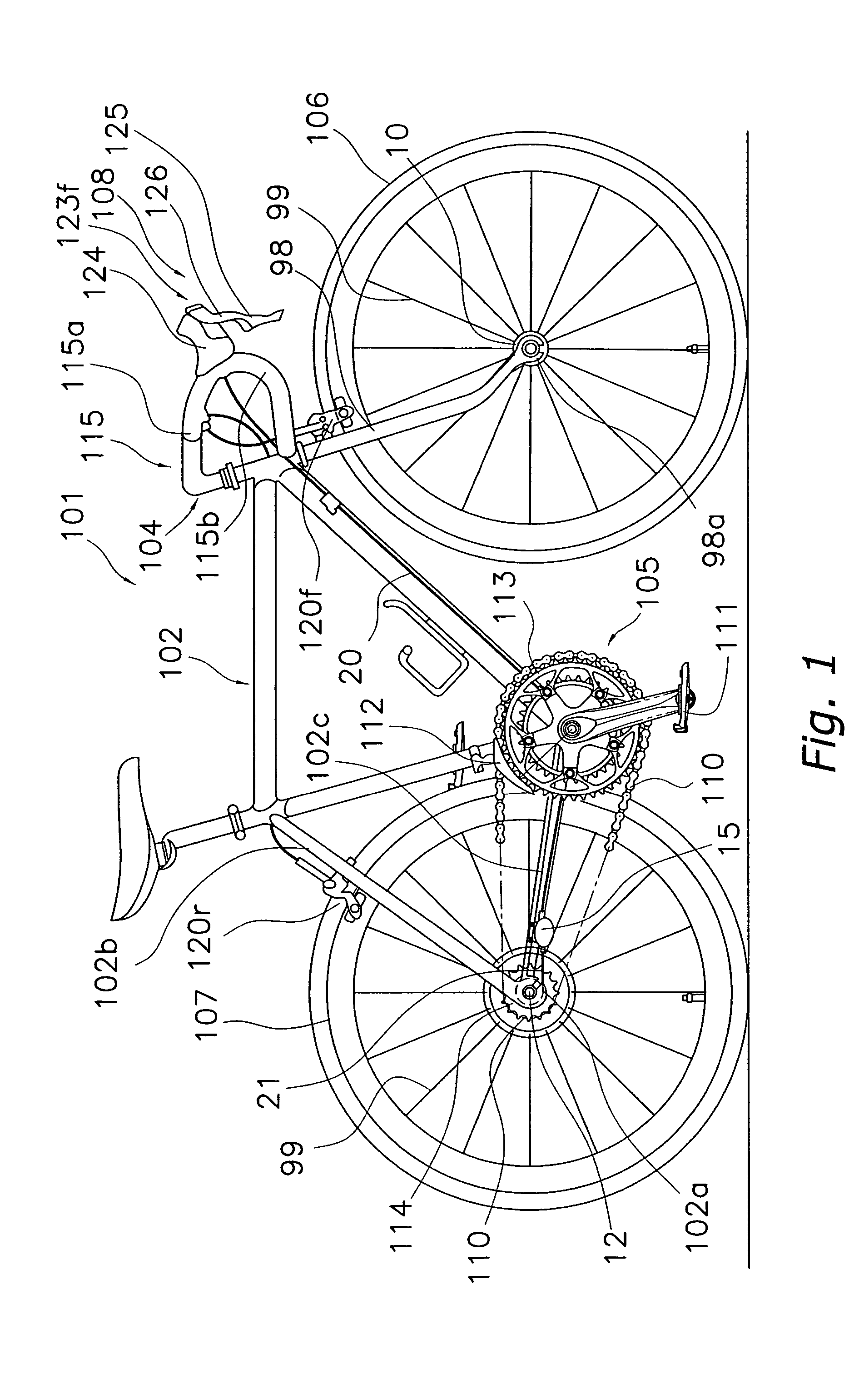
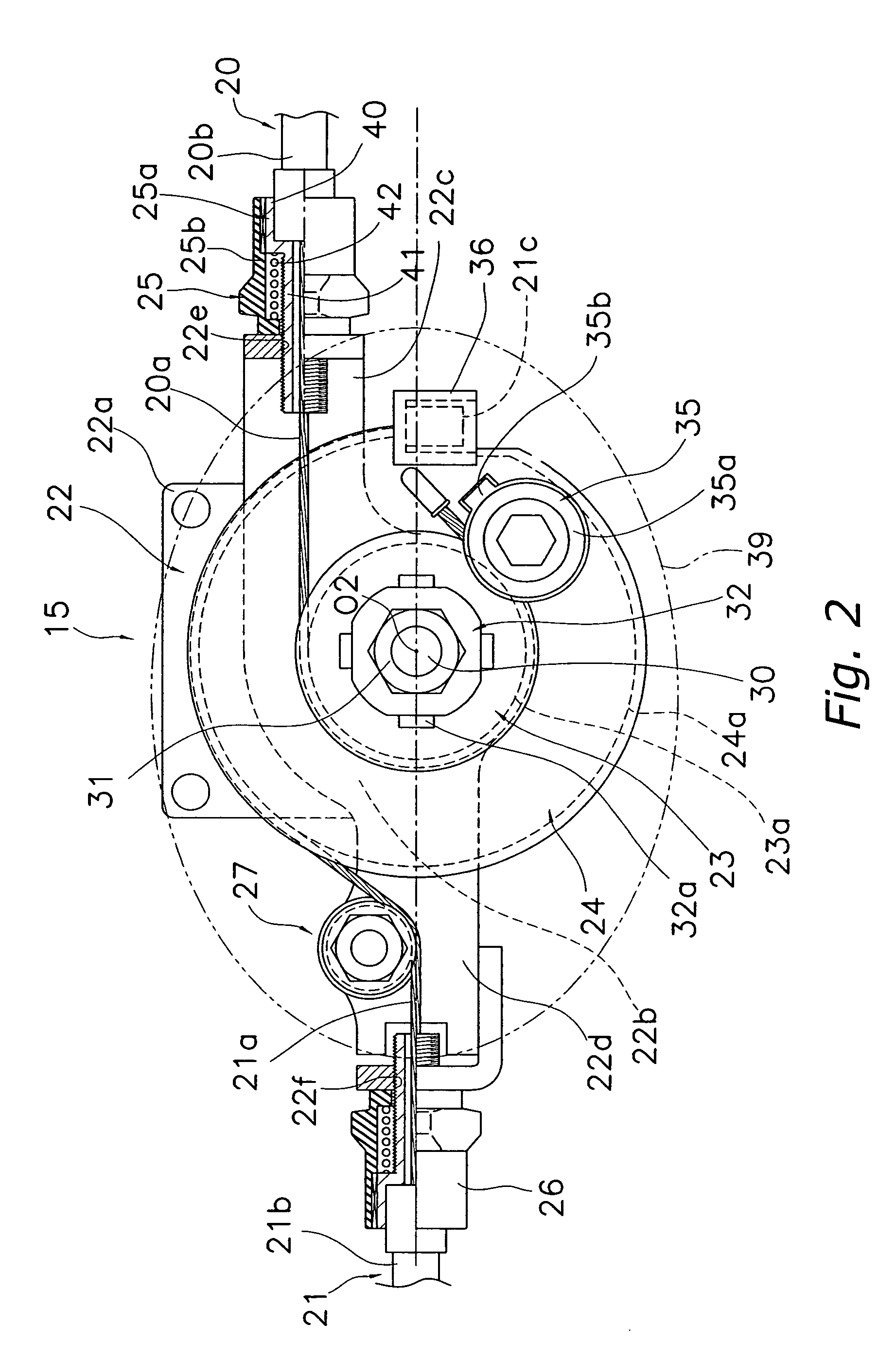
The present invention provides a cable winding conversion device that allows for easy placement of cables and a base member on a frame, especially a thin frame like a bicycle frame. The device includes a base member, a first winder, a second winder, a first cable mounting portion, and a second cable mounting portion. The first cable mounting portion is placed on the base member and directs the first inner wire of the first cable onto the first winder. The second cable mounting portion is placed on the base member and directs the second inner wire of the second cable onto the second winder. The distance between the cable and the pivoting center is determined by the distance between the first cable and the pivoting center, making it easier to place the cable on the frame. The device is simple and inexpensive to manufacture, assemble, and mount on a frame.

Problems solved by technology

When the cables and the pivoting center are widely misaligned, and the cables are separated from the pivoting center of the winders, it becomes difficult to place the cables and the base member on the frame, especially when the frame has relatively narrow tubes such as in a bicycle frame.
In other words, it becomes difficult to place the base member on the frame and the cables on the frame in optimal locations with these prior devices, especially when the cable winding conversion device is mounted on a frame that uses a lot of thin pipes like a bicycle because parts where the base member and cables can be mounted (placed) are limited.
Accordingly, due to the potential difficulty in mounting the cables and the base member on a thin frame, there is a risk that bracket(s) or other additional mounting structures will be needed on the frame to support the cables and / or the base member.

Method used


Image

  • Cable winding conversion device
  • Cable winding conversion device
  • Cable winding conversion device

Examples


second embodiment

[0065]Referring now to FIG. 4, a cable winding conversion device in accordance with a second embodiment of the present invention will now be explained. This second embodiment is identical to the first embodiment, except the cable winding conversion device of this second embodiment includes a modified circular first winder 153 and a second winder 154. The modified circular first winder 153 has its center offset from the rotation center 02. Thus, the cable winding conversion device of this second embodiment is designed to be mounted on the bicycle 101 in place of the cable winding conversion device 15 of the first embodiment between the first and second cables 20 and 21. In view of the similarity between the first and second embodiments, the parts of the second embodiment that are identical to the parts of the first embodiment will be given the same reference numerals as the parts of the first embodiment. Moreover, the descriptions of the parts of the second embodiment that are identi...

third embodiment

[0068]Referring now to FIG. 5, a cable winding conversion device in accordance with a third embodiment of the present invention will now be explained. This third embodiment is identical to the first embodiment, except the cable winding conversion device of this third embodiment includes a modified first winder 223 and a second winder 224. The modified first winder 223 is eccentrically shaped (e.g. cam shaped) relative to the rotation center 02, as opposed to being circular shaped as in the first embodiment. Thus, the cable winding conversion device of this third embodiment is designed to be mounted on the bicycle 101 in place of the cable winding conversion device 15 of the first embodiment between the first and second cables 20 and 21. In view of the similarity between the first and third embodiments, the parts of the third embodiment that are identical to the parts of the first embodiment will be given the same reference numerals as the parts of the first embodiment. Moreover, the...

fourth embodiment

[0071]Referring now to FIG. 6, a cable winding conversion device in accordance with a fourth embodiment of the present invention will now be explained. This fourth embodiment is identical to the first embodiment, except the cable winding conversion device of this fourth embodiment includes a modified cable mounting section 322c with a cable guide part 327. The modified cable mounting section 322c is arranged such that the first barrel adjuster 25 directs the first cable 20 (i.e. the first inner wire 20a and the first outer casing 20b) toward the rotation center 02 of the first and second winders 23 and 24. The cable guide part 327 then directs the inner wire 20a tangentially onto the first winder 23. In other words, the cable winding conversion device of this fourth embodiment includes a first cable mounting portion that is substantially identical to the second cable mounting portion (i.e. a mirror image). Thus, the cable winding conversion device of this fourth embodiment is design...


PUM


Abstract

A cable winding conversion device is provided that enables relatively easy placement on a frame such as a bicycle frame between a pair of cables. The cable winding conversion device basically includes a base member, a first winder, a second winder, a first cable mounting portion, and a second cable mounting portion. The base member is configured to be mounted to a frame. The first and second winders are rotatably mounted to the base member to wind first and second inner wires of the first and second cables. The second winder has at least a portion with a winding radius larger than the first winder. The first cable mounting portion directs the first cable. The second cable mounting portion directs the second cable. The second cable mounting portion includes a cable receiving opening that is directed toward a rotation center of the winders.

Description

CROSS-REFERENCE TO RELATED APPLICATIONS[0001]This application claims priority to Japanese Patent Application No. 2004-166171. The entire disclosure of Japanese Patent Application No. 2004-166171 is hereby incorporated herein by reference.BACKGROUND OF THE INVENTION[0002]1. Field of the Invention[0003]The present invention generally relates to a cable winding conversion device that is designed to be placed between first and second cables that have first and second inner wires slidably mounted within first and second outer casings, respectively. More specifically, the present invention relates to a cable winding conversion device with different winders for the different inner wires with at least one of the inner wires being directed toward the rotation center of the winders.[0004]2. Background Information[0005]A cable known as a Bowden cable has an outer casing that allows the passage of an inner wire. This type of cable is widely used as an operation cable in bicycles, motorcycles, a...

Claims


Application Information

Patent Timeline
Patent Type & Authority Patents(United States)
IPC IPC(8): F16C1/26B62K23/00B62K23/02B62M25/02
CPCB62K23/00B62M25/02Y10T74/20462
Inventor UENO, KOKEN
Owner SHIMANO INC
Learn More