Diagnosis and state monitoring of junctions, crossings, crossroads or rail joints by means of a rail vehicle

Active Publication Date: 2009-05-26
DEUTSCHE BAHN
View PDF17 Cites 22 Cited by
  • Summary
  • Abstract
  • Description
  • Claims
  • Application Information

AI Technical Summary

Benefits of technology

[0015]According to the invention, more preferably vibration accelerations on passing over of a rail vehicle are thus measured and evaluated true to the location. These are directly connected with the wear and functional state of the junction, crossing or crossroads, rail joint and track nonuniformities since increasing vibration accelerations are more preferably caused through growing deviations of their geometry from its required shape and its position from its required position. More preferably, rolling of a railway wheel over the frog gap in the case of rigid frogs consequently takes place increasingly “less gentle” with increasing wear. At the same time, high vibration accelerations mean high rates of energy introduction into individual components of the junction, crossing or crossroads as well as the rail joint and track nonuniformities which additionally promote and accelerate advancing of the wear. Rolling over instabilities of the junction, crossing or cross roads, the rail joint and track nonuniformities due to the design, together with their increasing wear or poor setting creates characteristically changing values of vibration acceleration on a wheel or wheel set of the vehicle rolling over. These vibration accelerations spread to the entire vehicle in accordance with dampings of the design of the vehicle caused by the design. In this way, growing deviations of the geometry from settings and attachments of components of the junction, crossing or crossroads as well as the rail joint and track nonuniformities create increasing vibration accelerations in the vehicle and vice versa.
[0023]Here, more preferably piezoelectric acceleration pickups are used as acceleration sensors. These are characterized by low weight, compact design and their robustness and long life.
[0025]A positioning device determines the location of the measured junction, crossing or crossroads as well as rail joints and track nonuniformities so that local assignment of the determined vibration accelerations to the corresponding measured junction, crossing or cross roads, rail joint and track nonuniformity can take place. Advantageous in this context is that upon occurrence of irregularities or exceeding of characteristic prescribed limit values of the vibration acceleration, maintenance personnel can be accurately directed to the respective conspicuous junction, crossing or crossroads, rail junction and track nonuniformity. As positioning device, a position indicator of the rail vehicle present in the rail vehicle is advantageously used in connection with the position of the acceleration pickup within the rail vehicle. This position indicator of the rail vehicle is performed more preferably by way of train control systems of the route travelled which inform the rail vehicle of its position on the route, more preferably a scheduled train influencing system (LZB) or a European Train Control System (ETCS), or by way of a satellite supported position indicating device.
[0026]Particularly advantageously a positioning device is used which in addition to a position indicator also provides an indication of the speed and the travel direction of the rail vehicle as is more preferably possible with a satellite supported position indicating device. As a result, the speed measuring device and the positioning device are combined into a single device so that a separate speed measuring device is no longer required.
[0028]Advantages of the method according to the invention and the device according to the invention more preferably are in the diagnosis and state monitoring of a junction, crossing or crossroads, rail joint and track nonuniformities between scheduled inspections or maintenance operations. Here, a first more accurate statement on the state of the junction, crossing or crossroads is made through a rapid and simple check. Thus, particularly timely, wear is detected and from its data a necessary maintenance date and maintenance effort forecast, as a result of which more preferably better medium term planning and optimization of the life cycle costs is guaranteed. In addition comparability with earlier measured values is possible.
[0033]A travelling comfort for passengers is increased through the invention,

Problems solved by technology

Rolling over instabilities of the junction, crossing or cross roads, the rail joint and track nonuniformities due to the design, together with their increasing wear or poor setting creates characteristically changing values of vibration acceleration on a wheel or wheel set of the vehicle rolling over.
In this way, growing deviations of the geometry from settings and attachments of components of the junction, crossing or crossroads as well as the rail joint and track nonuniformities create increasing vibration accelerations in the vehicle and vice versa.

Method used


Image

  • Diagnosis and state monitoring of junctions, crossings, crossroads or rail joints by means of a rail vehicle
  • Diagnosis and state monitoring of junctions, crossings, crossroads or rail joints by means of a rail vehicle
  • Diagnosis and state monitoring of junctions, crossings, crossroads or rail joints by means of a rail vehicle

Examples


Embodiment Construction

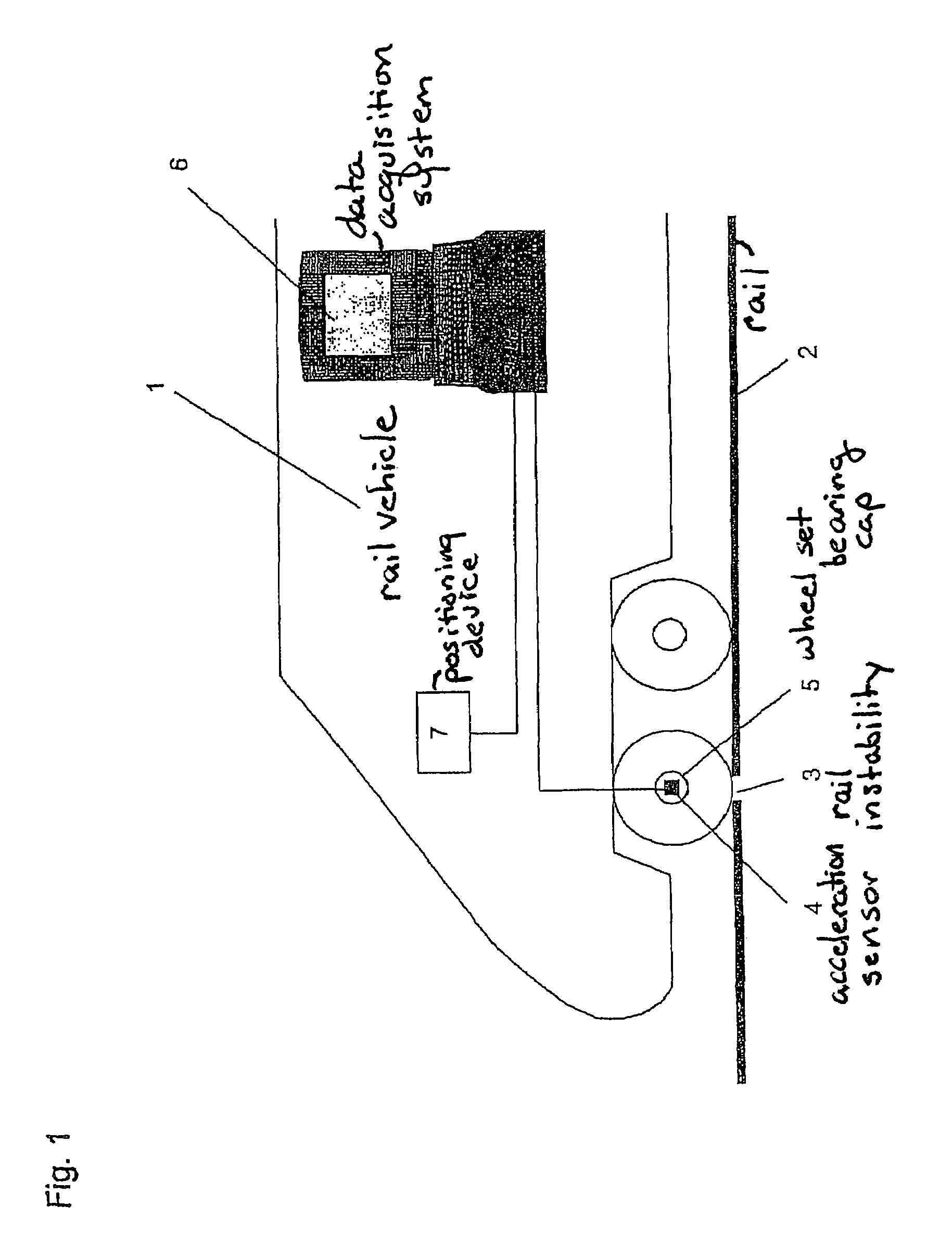
[0039]A particularly advantageous exemplary embodiment relates according to FIG. 1 to a rail vehicle 1 travelling over an instability 3 of a rail 2. The instability 3 of the rail 2 in this case presents an example of a frog gap of a junction with a rigid frog.

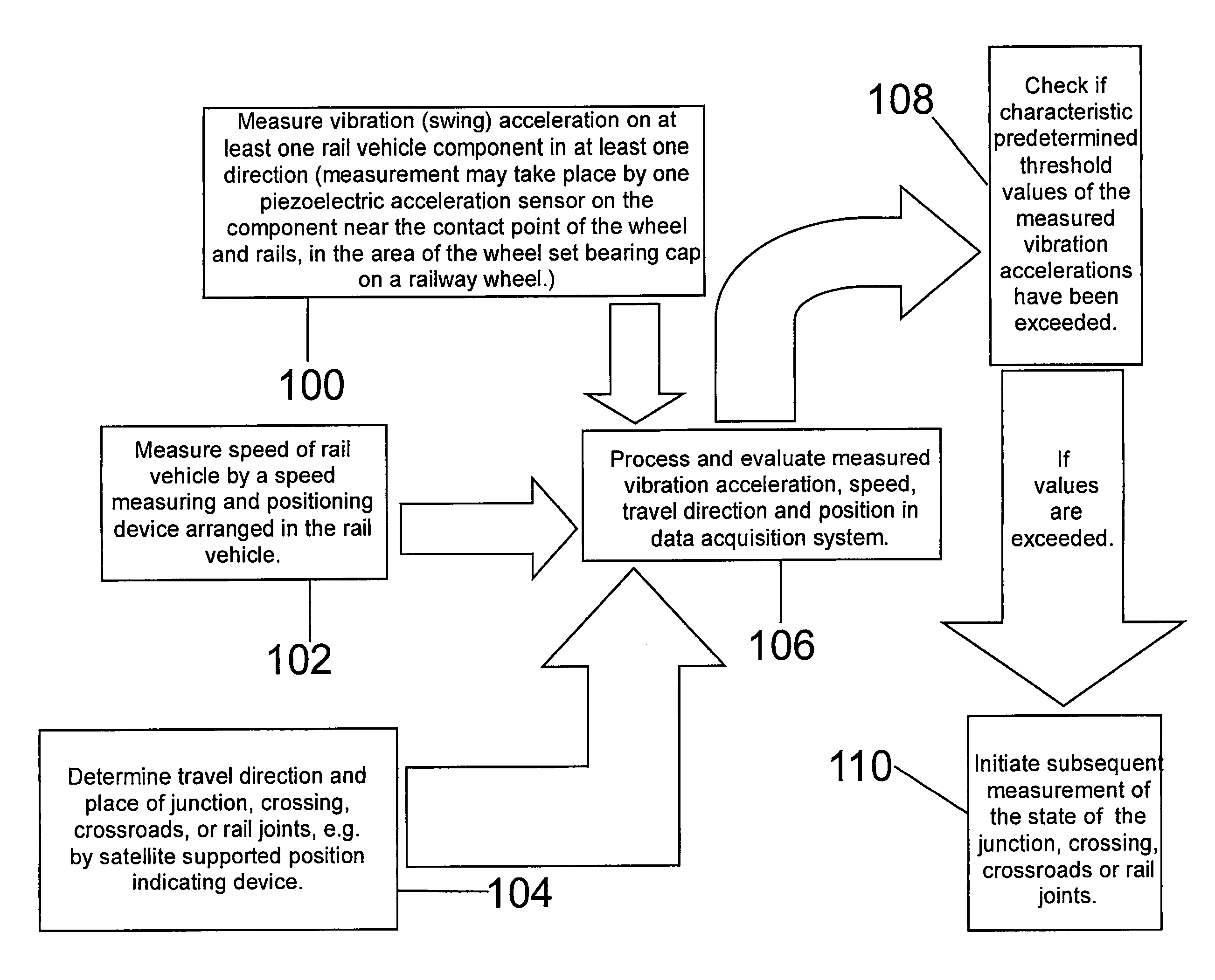
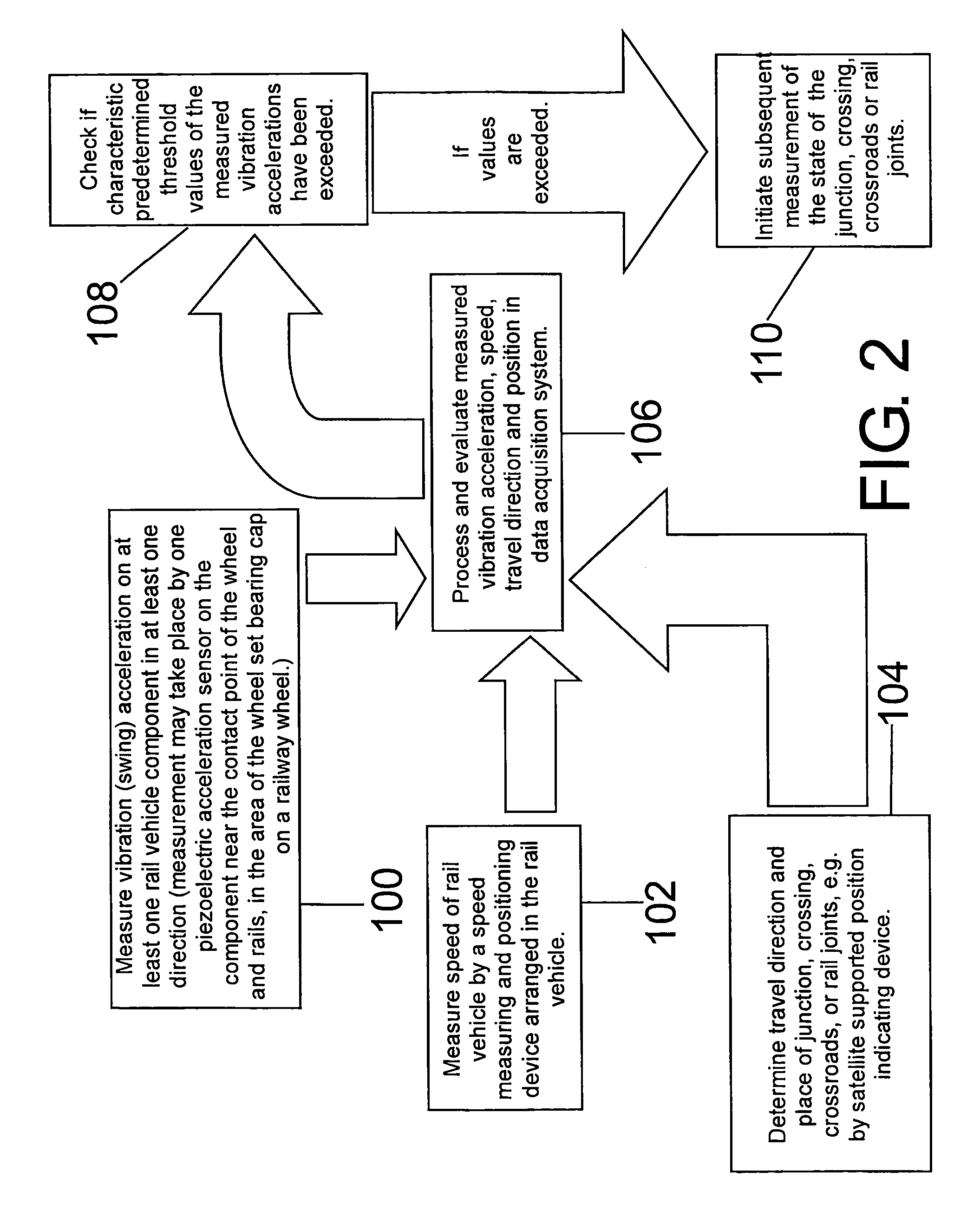
[0040]When the rail vehicle travels over the instability 3 with a certain speed and a certain travel direction an acceleration sensor 4, provided on a wheel set bearing cap 5 (or as closely as possible to the contact point proximity of wheel and rails) determines vibration accelerations to which the rail vehicle is subjected as a result of the travelling over. See FIG. 2, step 100. In addition, a positioning device 7, more preferably a satellite supported position indicating device, establishes the position, the speed and the travel direction of the rail vehicle. See FIG. 2, steps 102 and 104.

[0041]A data acquisition system 6 performs signal processing and signal storage of the measurement signals of the acceleration sensor 4 a...


PUM


Abstract

A method and a device for diagnosis and state monitoring of a wear and functional state of a junction, a crossing, a crossroads, rail joints, and / or track nonuniformities of a rail traffic path made of several tracks measures and stores swing acceleration in at least one direction when overtaking a rail vehicle on a junction, crossings or crossroads, in addition to rail joints or track nonuniformities on at least one rail vehicle component, the swing acceleration being produced on the rail vehicle component when overtaking the rail vehicle at the junction, crossing or crossroads, rail joints, track nonuniformites. The method also measures and stores the rail vehicle speed and determines and stores the travel direction and the place of the junction, crossing or crossroads, rail joints, track nonuniformities, carries out a control as to whether characteristic, predetermined threshold values of the measured swing accelerations have been exceeded.

Description

CROSS REFERENCE TO RELATED APPLICATIONS[0001]Applicants claim priority under 35 U.S.C. §119 of German Application No. 10 2004 045 457.4 filed Sep. 20, 2004. Applicants also claim priority under 35 U.S.C. §365 of PCT / EP2005 / 004837 filed May 4, 2005. The international application under PCT article 21(2) was not published in English.BACKGROUND OF THE INVENTION[0002]1. Field of the Invention[0003]This application is the National Stage of PCT / EP2005 / 004837 filed May 4, 2005, which claims priority under 35 U.S.C. §119 of German Application No. 10 2004 045 457.4 filed Sep. 20, 2004. The international application under PCT article 21(2) was not published in English.DESCRIPTION[0004]The invention relates to a method and to a device for the diagnosis and state monitoring of wear and functional state of a junction and / or a crossing and / or a crossroads and / or rail joints and / or track nonuniformities of a rail traffic path which is made up of several tracks.[0005]2. Description of the Related Ar...

Claims


Application Information

Patent Timeline
IPC IPC(8): B61L23/04G06F17/00
CPCB61K9/08B61L23/045B61L2205/04
Inventor ZOLL, ANDREASLUKE, DANIEL
Owner DEUTSCHE BAHN
Why Eureka
Try Eureka