
Shingle with reinforcement layer

a technology of reinforcement layer and shingle, which is applied in the direction of transportation and packaging, traffic signals, roads, etc., can solve the problems of internal shingle formation, insufficient asphaltic material on the surface of the shingle, and inability to withstand certain wind conditions,

Inactive Publication Date: 2009-05-26
CERTAINTEED CORP
View PDF33 Cites 49 Cited by
  • Summary
  • Abstract
  • Description
  • Claims
  • Application Information

AI Technical Summary

Benefits of technology

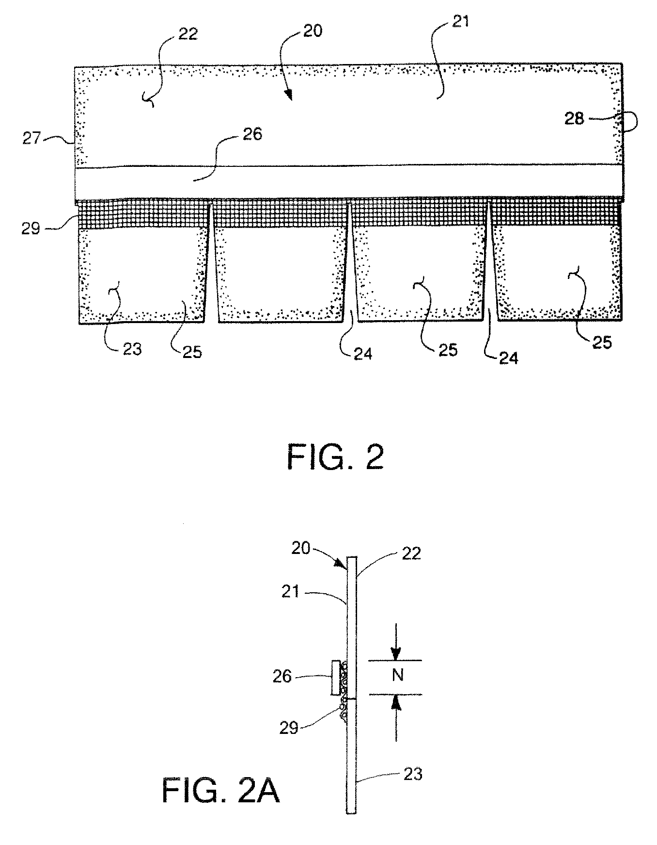
"The present invention provides a shingle with a reinforcement layer on the rear surface of the shingle. This reinforcement layer is made of a scrim material and extends into either or both of the tab portion of the shingle and the headlap portion of the shingle, as well as a nailing zone or other fastening zone of the shingle. The technical effect of this invention is to provide a stronger and more durable shingle that can withstand wind and other weather conditions, as well as increased pressure from heavy snow accumulation. Additionally, the method of making shingles in accordance with this invention is also provided."

Problems solved by technology

On occasion, under strong winds, the tabs can bend upwardly in amounts sufficient that the inherent, internal resistance to substantial bending and perhaps cracking, can be overcome, in that the mat that is formed internally of the shingle, and the asphaltic material on the surfaces of the shingle, may not be sufficient to withstand certain wind conditions.
Various approaches have been made to resist shingle failure via cracking and the like, not all with substantial success.
However, such adhesive sometimes dries out, or becomes brittle over time, offering reduced adhesion.
In other cases, strong wind conditions can exist during high temperature situations when such adhesive located under tabs remains soft, and thus the adhesive does not function in its intended manner.
Other approaches have resorted to thickening the mat and / or asphaltic material, to offer internal resistance to bending, but nonetheless, failures due to wind-related bending of tabs of shingle continue to exist.

Method used


Image

  • Shingle with reinforcement layer
  • Shingle with reinforcement layer
  • Shingle with reinforcement layer

Examples


Embodiment Construction

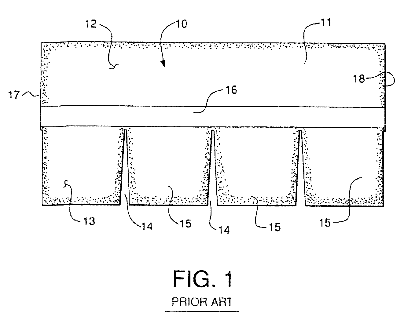
[0024]Referring now to the drawings in detail, reference is first made to FIG. 1, wherein a prior art shingle is illustrated as comprising a shingle generally designated by the numeral 10, constructed as a mat of preferably fiberglass mesh, having asphalt, or some other form of bitumen material impregnated therein, and forming layers on each surface thereof, with a granular material on each exposed surface. On the upper exposed surface, will be granules of a size desired to resist sun and other weather conditions, and on the opposite, or undersurface 11, there will be preferably smaller granules of a mica, sand or like material, for example. The shingle 10 has a headlap portion 12 and a tab portion 13, having slotted openings 14 dividing the tab portion 13 into a number of discrete tabs 15. On the undersurface 11 there is provided preferably but optionally a sheet of release paper or tape 16, which is removed when the shingle is installed on a roof, but which, for stacking shingles ...


PUM

PropertyMeasurementUnit
widthaaaaaaaaaa
widthaaaaaaaaaa
widthaaaaaaaaaa

Abstract

A shingle and a method of making it is provided in which the rear surface of the shingle is provided with an attached reinforcement layer through which fasteners may be applied when the shingle is applied to a roof.

Description

CROSS-REFERENCE TO RELATED APPLICATIONS[0001]This is a Continuation-in-Part of U.S. application Ser. No. 10 / 871,911, filed Jun. 18, 2004, now U.S. Pat. No. 7,118,794, which in turn is a continuation of Ser. No. 10 / 288,747, filed Nov. 6, 2002, now U.S. Pat. No. 6,758,019.BACKGROUND OF THE INVENTION[0002]In the manufacture of shingles, it has been known that when shingles are subjected to strong winds, the winds can engage the lower edges or tab portions of the shingles, and bend them upwardly.[0003]On occasion, under strong winds, the tabs can bend upwardly in amounts sufficient that the inherent, internal resistance to substantial bending and perhaps cracking, can be overcome, in that the mat that is formed internally of the shingle, and the asphaltic material on the surfaces of the shingle, may not be sufficient to withstand certain wind conditions.[0004]Various approaches have been made to resist shingle failure via cracking and the like, not all with substantial success.[0005]For...

Claims


Application Information

Patent Timeline
Patent Type & Authority Patents(United States)
IPC IPC(8): E04D1/22E04D1/28B32B11/02E04D1/00E04D1/26
CPCB32B5/24E04D1/26E04D1/22E04D1/28E04D1/20E04D1/34B32B11/02Y10T428/25B32B2250/02B32B2255/20B32B2260/021B32B2260/042B32B2262/101B32B2307/5825B32B2395/00B32B2419/06E04D2001/005Y10T428/24372Y10T156/10C09D195/00E04D2001/3452E04D2001/3482
Inventor KALKANOGLU, HUSNU M.KOCH, STEPHEN A.
Owner CERTAINTEED CORP
Learn More