
Apparatus and method for handling pipe sections

a technology of apparatus and pipe section, applied in the direction of drilling casings, geothermal energy generation, drilling pipes, etc., can solve the problems of time-consuming, difficult to move the selected pipe section, and the procedure must be implemented at the drilling site. , to achieve the effect of convenient movement of the selected pipe section

Active Publication Date: 2009-05-26
MARL TECH
View PDF26 Cites 24 Cited by
  • Summary
  • Abstract
  • Description
  • Claims
  • Application Information

AI Technical Summary

Benefits of technology

"The present invention is a pipe section handling apparatus and method for use with a drilling head in drilling operations. The apparatus and method allow for the movement of pipe sections between a storage location and a drilling head interface position. The apparatus includes a pipe storage bin, a pipe transfer device, and a pipe handling device. The apparatus and method can be used in drilling operations, non-drilling applications, and geotechnical engineering applications. The technical effects of the invention include improved efficiency in drilling operations, increased flexibility in drilling equipment usage, and reduced risk of damage to drilling equipment."

Problems solved by technology

Relatively less robust and less sophisticated drilling rigs may often be used for drilling water wells and in geothermal heat exchange applications, since these boreholes tend to be relatively shallow and small in diameter.
A disadvantage, however, of using pipe sections to construct a drill string is that procedures must be implemented at the drilling site to transfer the pipe sections to and from the derrick and to connect and disconnect the pipe sections to and from the derrick as drilling progresses.
These procedures are often time consuming and require the participation of several drilling personnel.
In addition, these procedures may be inherently dangerous, since they involve the manipulation of the pipe sections, which although relatively short, are also relatively heavy and somewhat unwieldy.
As a result of the disadvantages associated with using pipe sections to construct drill strings, efforts have been made to automate the handling of pipe sections at the drilling site between the location where the pipe sections are stored and the derrick.

Method used


Image

  • Apparatus and method for handling pipe sections
  • Apparatus and method for handling pipe sections
  • Apparatus and method for handling pipe sections

Examples


Embodiment Construction

[0144]The present invention is an apparatus and method for handling pipe sections, preferably for use in association with a drilling head, and preferably for drilling purposes.

[0145]The apparatus and the drilling head may be used to drill any type of borehole, which borehole may be used for any purpose. In the preferred embodiment the apparatus, the drilling head and a derrick are used to drill boreholes for use in a geothermal heat exchange system. However, the apparatus and method may be used in connection with drilling boreholes for other purposes such as for mineral exploration, for geotechnical, environmental or geo-environmental engineering purposes, for use as water wells, or in connection with other similar drilling requirements.

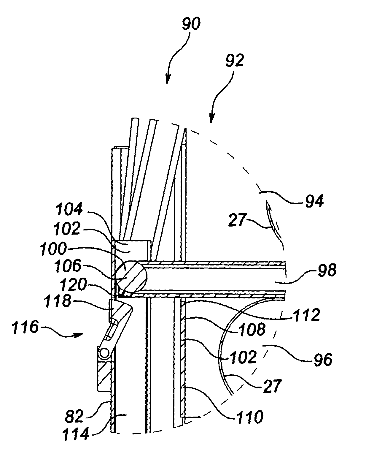
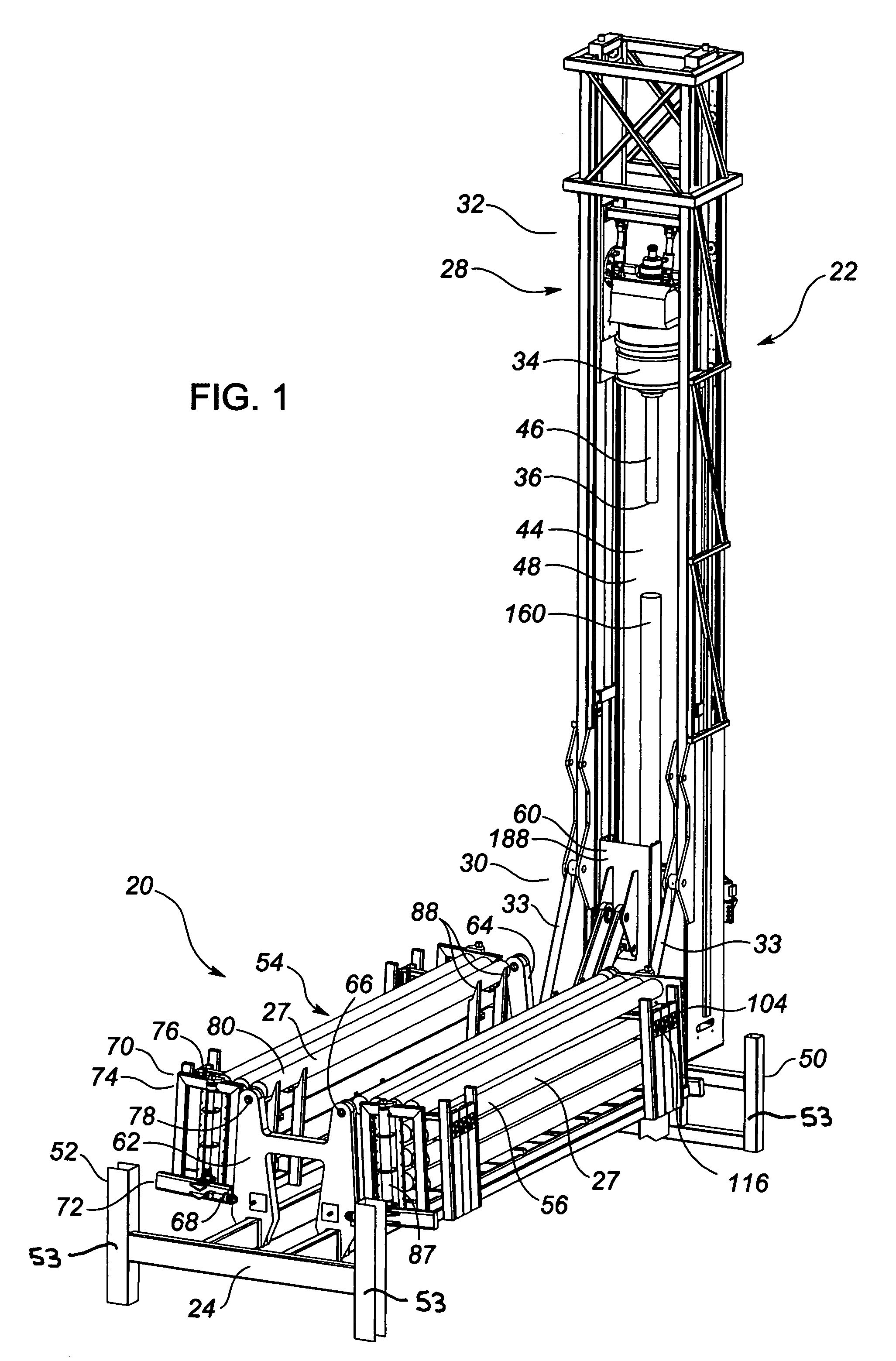
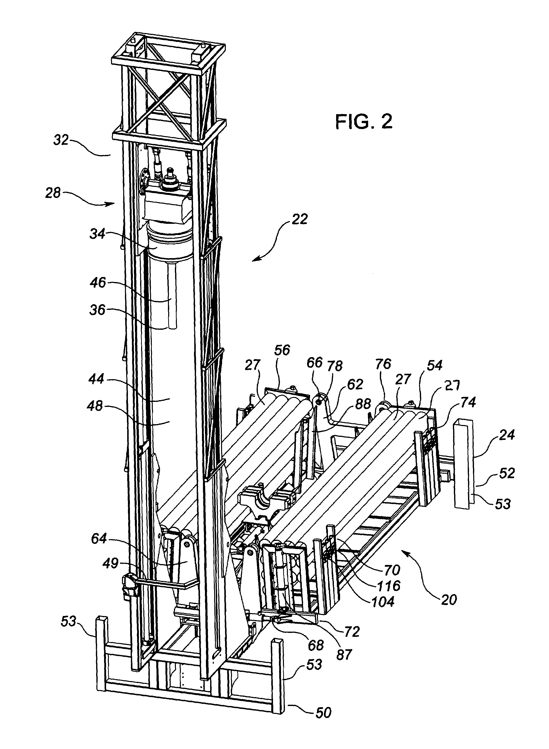
[0146]Referring to FIGS. 1-3, in the preferred embodiment the apparatus (20) and a derrick (22) are configured together on a chassis (24). The chassis (24) is in turn mounted on a truck (26) so that the apparatus (20) and the derrick (22) are mobile....


PUM


Abstract

An apparatus and method for handling pipe sections, preferably for use with a drilling head. The apparatus includes a storage bin defining a substantially fixed bin dispensing position, a transfer device for individually transferring a pipe section between the bin dispensing position and a pipe transfer position, and a handling device for individually moving the pipe section between the pipe transfer position and a drilling head interface position. The method includes presenting a pipe section to the bin dispensing position, moving the transfer device to the bin dispensing position to engage the pipe section at the bin dispensing position, transferring the pipe section with the transfer device from the bin dispensing position to the pipe transfer position, engaging the pipe section with the handling device at the pipe transfer position, and moving the pipe section with the handling device from the pipe transfer position to the drilling head interface position.

Description

TECHNICAL FIELD[0001]An apparatus and a method for handling pipe sections.BACKGROUND OF THE INVENTION[0002]Boreholes may be drilled in the earth for many different purposes. As one example, boreholes may be drilled for the purpose of recovering oil and / or gas from subterranean formations. As a second example, boreholes may be drilled for use as water wells. As a third example, boreholes may be drilled for geotechnical, environmental or geo-environmental engineering purposes. As a fourth example, boreholes may be drilled for mineral exploration purposes.[0003]A relatively recent development has been the drilling of boreholes for use in geothermal heat exchange systems. In a geothermal heat exchange system, the ground is used as both a heat source and a heat sink as an alternative to a boiler, furnace, air conditioner etc. in a conventional HVAC system. A geothermal heat exchange system typically involves the use of one or more “earth loops”, which are constructed by drilling a boreho...

Claims


Application Information

Patent Timeline
Patent Type & Authority Patents(United States)
IPC IPC(8): E21B19/00E21B19/14
CPCE21B7/02E21B19/155Y02E10/10
Inventor INNES, RONALD W.ELFORD, DUSTYN J.FOSTER, RONALD E.HACKETT, JOHN T.NGUYEN, TAN N.TEEUWSEN, DANIEL P.
Owner MARL TECH
Learn More