
Incremental placement during physical synthesis

a technology of physical synthesis and placement, applied in the field of circuit design, can solve the problems of one or more regions of the circuit design being implemented in a less than optimal fashion, one or more regions of the circuit design being affected in terms of timing, and one or more regions of the circuit design not meeting established timing requirements

Active Publication Date: 2009-05-19
XILINX INC
View PDF7 Cites 12 Cited by
  • Summary
  • Abstract
  • Description
  • Claims
  • Application Information

AI Technical Summary

Benefits of technology

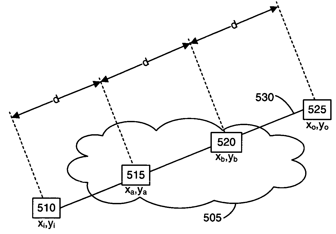
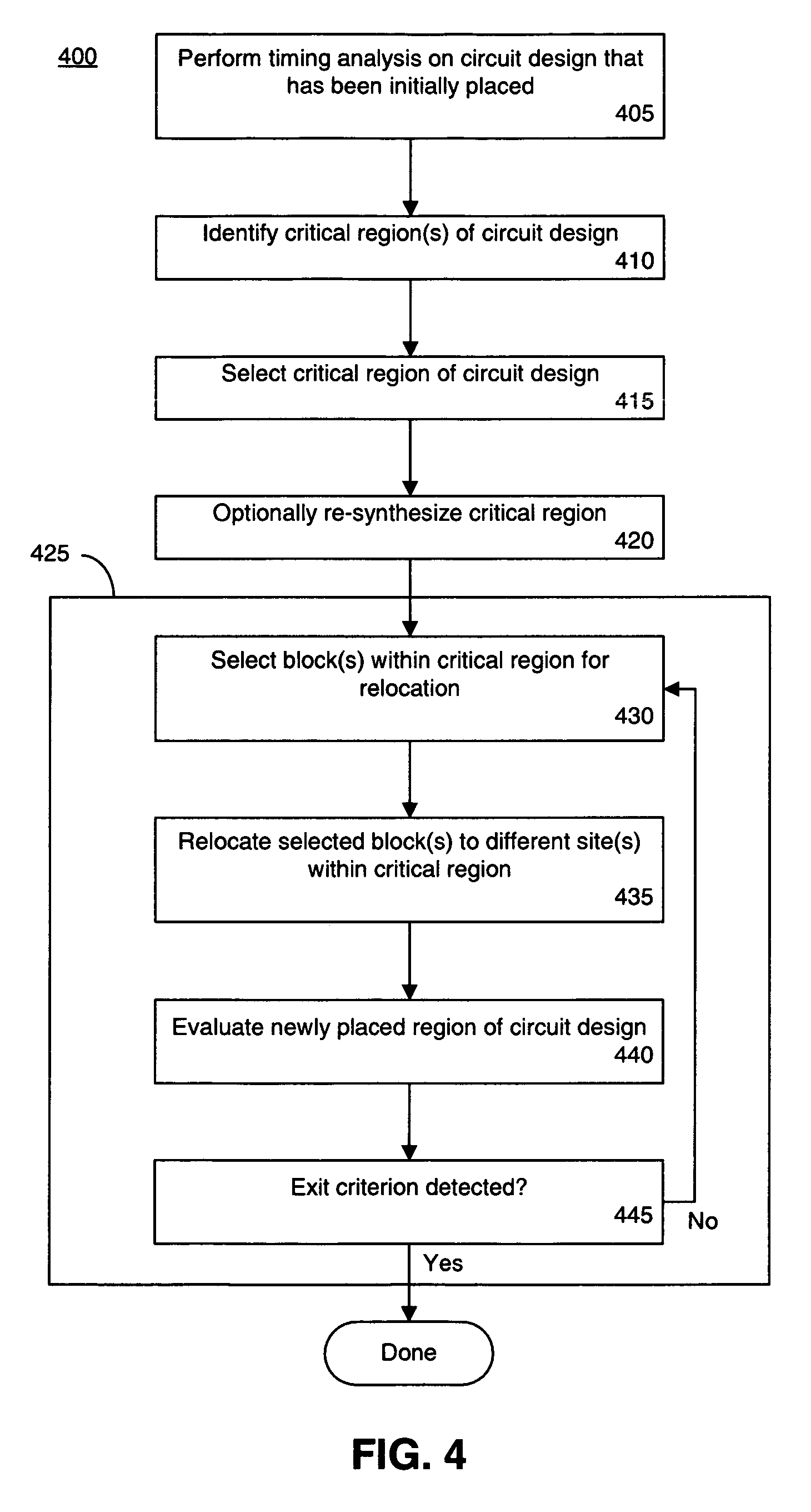
The present invention provides a method and article of manufacture for optimizing selected regions of a circuit design. The method involves identifying a critical region in the circuit design, which can include input and output blocks, and relocating these blocks to different positions within the critical region. The evaluation of the relocation is done based on a cost function, and the process continues until a predetermined exit criterion is met. The critical region can have a predetermined functionality, and the method can also include re-synthesizing the critical region while preserving its functionality. The invention allows for efficient optimization of circuit designs, improving their performance and reliability.

Problems solved by technology

This re-synthesis accounts for delays (or estimates of delays) of wires used to interconnect the various blocks of the circuit design on the target device.
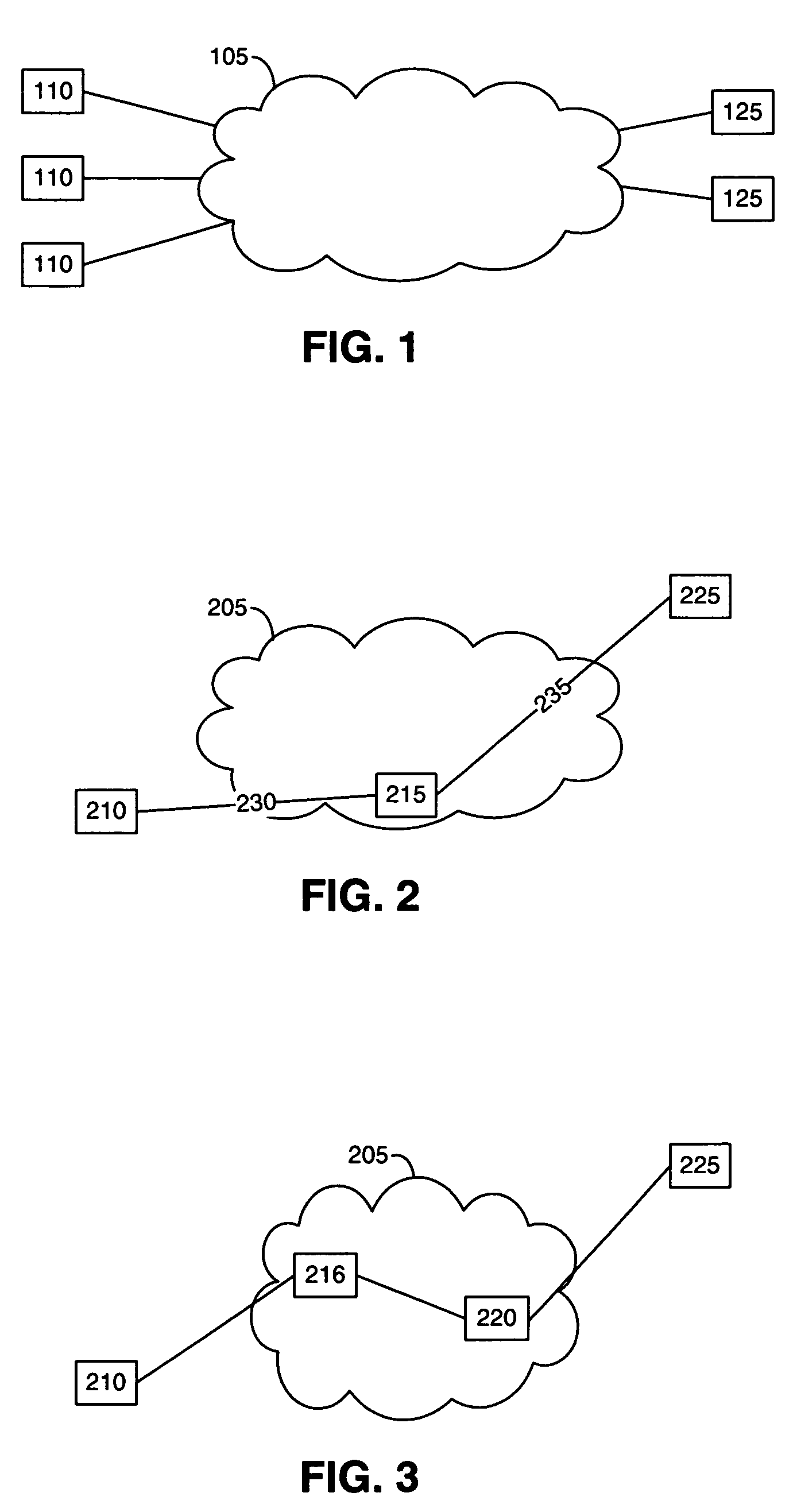
With a view on global optimization, however, it often is the case that one or more regions of the circuit design are implemented in a less than optimal fashion.
If wire length is valued too highly, one or more regions of the circuit design may suffer in terms of timing.
That is, in an effort to reduce the total wire length of the circuit design, one or more regions of the circuit design may not meet established timing requirements.
This iterative process, however, can be very time consuming, particularly since the entire circuit design, comprising upwards of thousands of netlist regions, is optimized during physical synthesis.

Method used


Image

  • Incremental placement during physical synthesis
  • Incremental placement during physical synthesis
  • Incremental placement during physical synthesis

Examples


Embodiment Construction

[0026]While the specification concludes with claims defining the features of the invention that are regarded as novel, it is believed that the invention will be better understood from a consideration of the description in conjunction with the drawings. As required, detailed embodiments of the present invention are disclosed herein; however, it is to be understood that the disclosed embodiments are merely exemplary of the invention, which can be embodied in various forms. Therefore, specific structural and functional details disclosed herein are not to be interpreted as limiting, but merely as a basis for the claims and as a representative basis for teaching one skilled in the art to variously employ the inventive arrangements in virtually any appropriately detailed structure. Further, the terms and phrases used herein are not intended to be limiting but rather to provide an understandable description of the invention.

[0027]The present invention includes a technique which allows circ...


PUM


Abstract

A method of optimizing a portion of a circuit design for a target device can include identifying a critical region from a plurality of regions after an initial placement of the circuit design. The critical region can be defined, at least in part, by at least one input block and at least one output block. Blocks of the critical region can be relocated to different sites within the critical region. The method further can include evaluating the relocation of blocks of the critical region according to a cost function and continuing to relocate blocks and evaluate the relocation of blocks in the critical region until at least one exit criterion is met.

Description

BACKGROUND[0001]1. Field of the Invention[0002]The present invention relates to circuit design and, more particularly, to optimizing portions of a circuit design for a target device.[0003]2. Description of the Related Art[0004]Synthesis refers to the process of translating an abstract representation of a circuit design into a physical implementation of that circuit design on some variety of electronic device, such as a programmable logic device (PLD). The abstract representation of the circuit design usually is specified in programmatic form using a Hardware Description Language (HDL). On a more detailed level, synthesis of a circuit design refers to both logic synthesis and physical synthesis.[0005]In general, logic synthesis refers to the translation of a Register Transfer Level (RTL) representation of a circuit design written in HDL into a gate-level representation of the circuit design. The gate-level representation is often specified as a netlist of logic primitives. Logic synt...

Claims


Application Information

Patent Timeline
Patent Type & Authority Patents(United States)
IPC IPC(8): G06F17/50
CPCG06F30/392
Inventor SINGH, AMITCHAUDHARY, KAMAL
Owner XILINX INC
Learn More