Electron emission device and electron emission display having the electron emission device

a technology of electron emission display and electron emission device, which is applied in the manufacture of electrode systems, electric discharge tubes/lamps, and discharge tubes luminescnet screens, etc., can solve the problems of reducing the light emission uniformity along the length of the first electrode of the electron emission display, reducing etc., to enhance the light emission uniformity and enhance the electron emission uniformity

Inactive Publication Date: 2009-05-19
SAMSUNG SDI CO LTD
View PDF14 Cites 0 Cited by
  • Summary
  • Abstract
  • Description
  • Claims
  • Application Information

AI Technical Summary

Benefits of technology

[0010]It is therefore a feature of an embodiment of the present invention to provide an electron emission device having enhanced electron emission uniformity.
[0011]It is therefore another feature of an embodiment of the present invention to provide an electron emission display having an electron emission device capable of providing enhanced light emission uniformity.

Problems solved by technology

Such a difference in line resistance between the first and second electrodes may reduce the electron emission uniformity despite the use of a resistive layer, thereby decreasing the light emission uniformity in the pixel units along the length of the first electrode of the electron emission display.

Method used


Image

  • Electron emission device and electron emission display having the electron emission device
  • Electron emission device and electron emission display having the electron emission device
  • Electron emission device and electron emission display having the electron emission device

Examples


examples

[0060]An electron emission display according to an embodiment of the present invention was formed (Example 1) and compared to a conventional electron emission display employed in a Cathode-Ray Tube (CRT) of the National Television System Committee (NTSC) (Comparative Example 1) in terms of color coordinates according to the color scale of the Commission Internationale de l'Eclairage (CIE) and reproduction thereof. The comparison results are summarized below in Table 1.

[0061]

TABLE 1Example 1Comparative Example 1Color coordinatesxyxyRed0.6350.3350.5750.354Green0.2750.6050.2870.524Blue0.1420.0650.1650.105Color Reproduction72.8%44.7%

[0062]As can be seen in Table 1, the color coordinates in Example 1 have values that are closer to pure red, green, and blue colors as compared to the color coordinates of the Comparative Example 1. Accordingly, the color reproduction upon combination of the red, green, and blue colors in Example 1 exhibits a value of 72.8% as compared to the value of 44.7% ...


PUM


Abstract

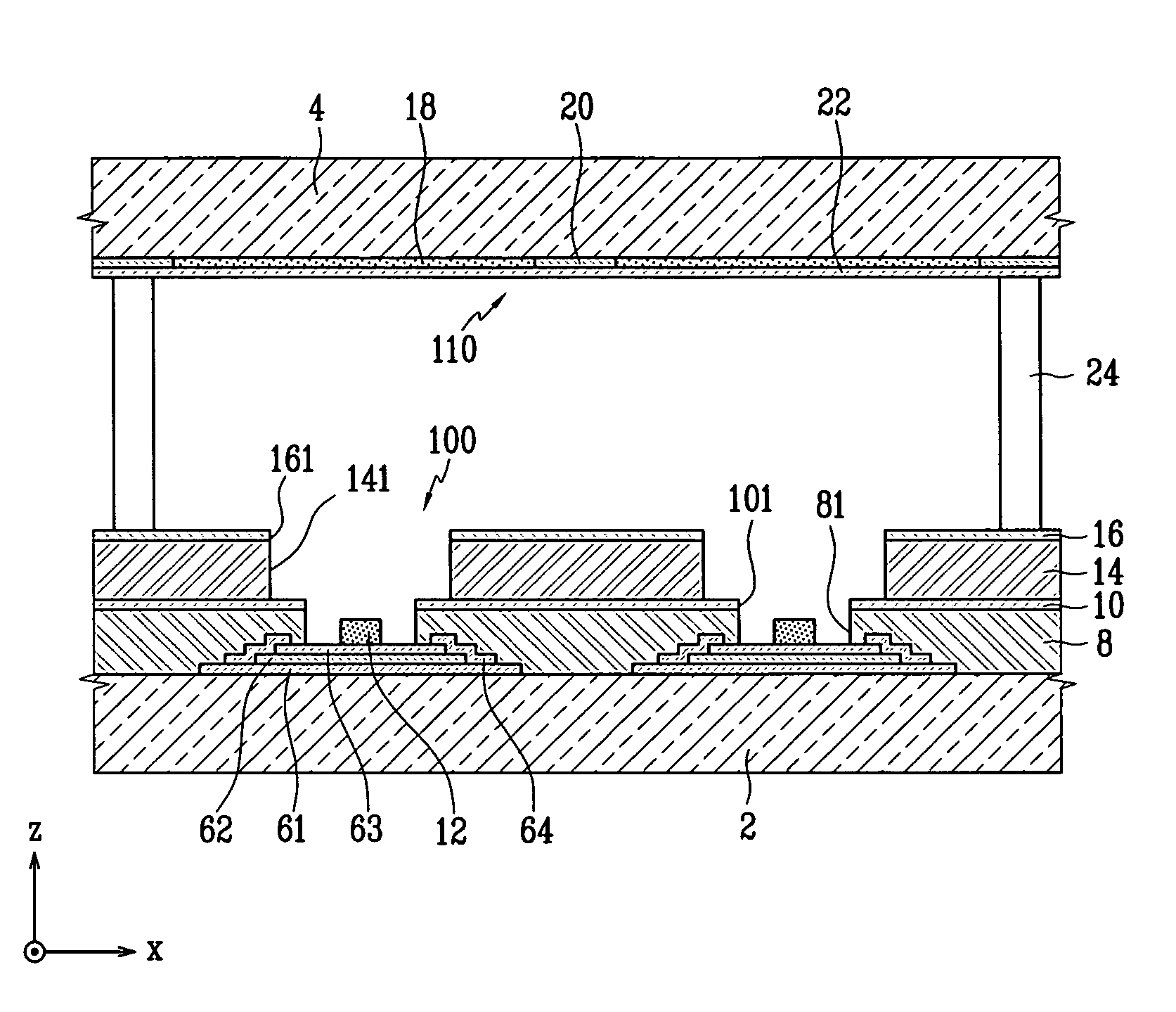
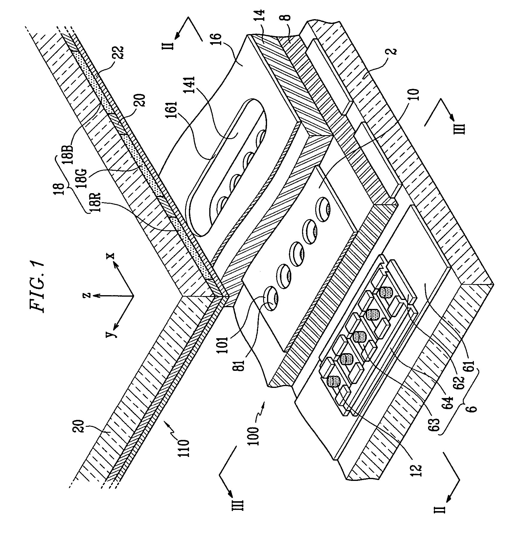
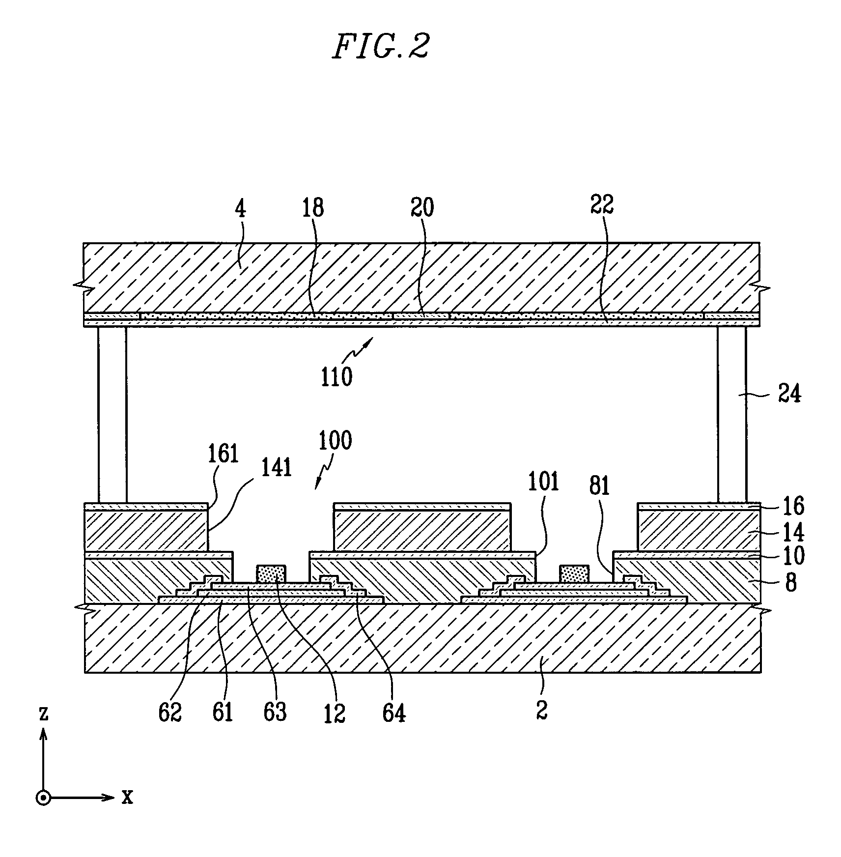
An electron emission device that includes a substrate, at least one electron emission region, and at least one cathode electrode disposed on the substrate and electrically connected to the electron emission region, wherein the cathode electrode has a first electrode, a plurality of second electrodes on the first electrode, a sub-insulation layer between the first and second electrodes, and a resistive layer electrically connected to the first and second electrodes.

Description

BACKGROUND OF THE INVENTION[0001]1. Field of the Invention[0002]The present invention relates to an electron emission device and an electron emission display employing the same. In particular, the present invention relates to an electron emission device having enhanced electron emission uniformity.[0003]2. Description of the Related Art[0004]In general, electron emission devices refer to devices that extract electrons from a cathode electrode, hot or cold, into vacuum. Such devices may be combined with a light emission unit and an anode electrode to form electron emission displays.[0005]Electron emission devices employing cold cathodes refer to devices having cathode electrodes that, instead of employing heat, emit electrons by application of a strong electric field, i.e., drive voltage, between the cathode and gate electrodes. An arrangement of a plurality of such cathode and gate electrodes on a substrate with electron emission regions therebetween may form an electron emission de...

Claims


Application Information

Patent Timeline
Patent Type & Authority Patents(United States)
IPC IPC(8): H01J1/62H01J9/24H01J1/02H01J63/04
CPCH01J1/304H01J3/022H01J31/127H01J1/30
Inventor JEON, SANG-HOLEE, SANG-JOCHO, JIN-HUIAHN, SANG-HYUCKHONG, SU-BONGJEA, BYUNG-GIL
Owner SAMSUNG SDI CO LTD
Why Eureka
Try Eureka