
Enhanced thermal deformation resisting bearing of electric motor

a technology electric motor, which is applied in the direction of positive displacement liquid engine, piston pump, liquid fuel engine, etc., can solve the problems of increased noise volume, internal diameter error, rough edge, etc., to improve the lubricating effect of the axle, facilitate the installation of the electric motor, and enhance the effect of thermal deformation resistan

Inactive Publication Date: 2009-05-19
TEK CHAIN TECH
View PDF1 Cites 1 Cited by
  • Summary
  • Abstract
  • Description
  • Claims
  • Application Information

AI Technical Summary

Benefits of technology

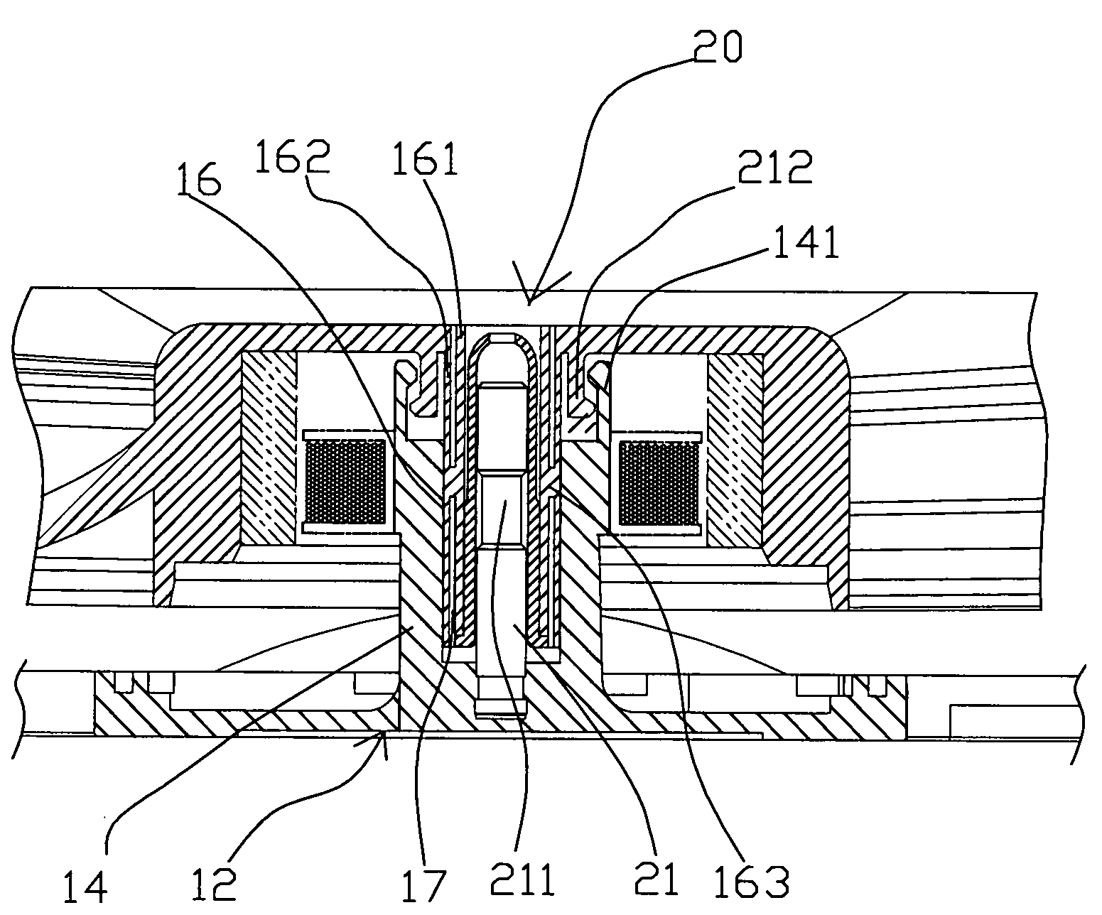
"The present invention provides an improved thermal deformation resisting bearing for an electric motor. The bearing is divided into inner and outer layers with a connecting portion to maintain an appropriate interval between them. This prevents deformation or shifting of the axle due to high temperatures during continuous rotations. The outer layer of the bearing has elasticity to securely hold the axle sleeve. The bearing also insulates high-temperature heat and prevents it from being conducted to the axle sleeve, which prevents deformation or expansion of the axle. A groove is built at the periphery of the axle to maintain a minimum gap between the bearing and the axle. Lubricant oil is filled into the space between the groove and the connecting portion for improved lubrication. An embedded groove is created at the internal side of the opening at the free end of the axle sleeve, which facilitates the installation of the electric motor and secure the rotor and stator with each other."

Problems solved by technology

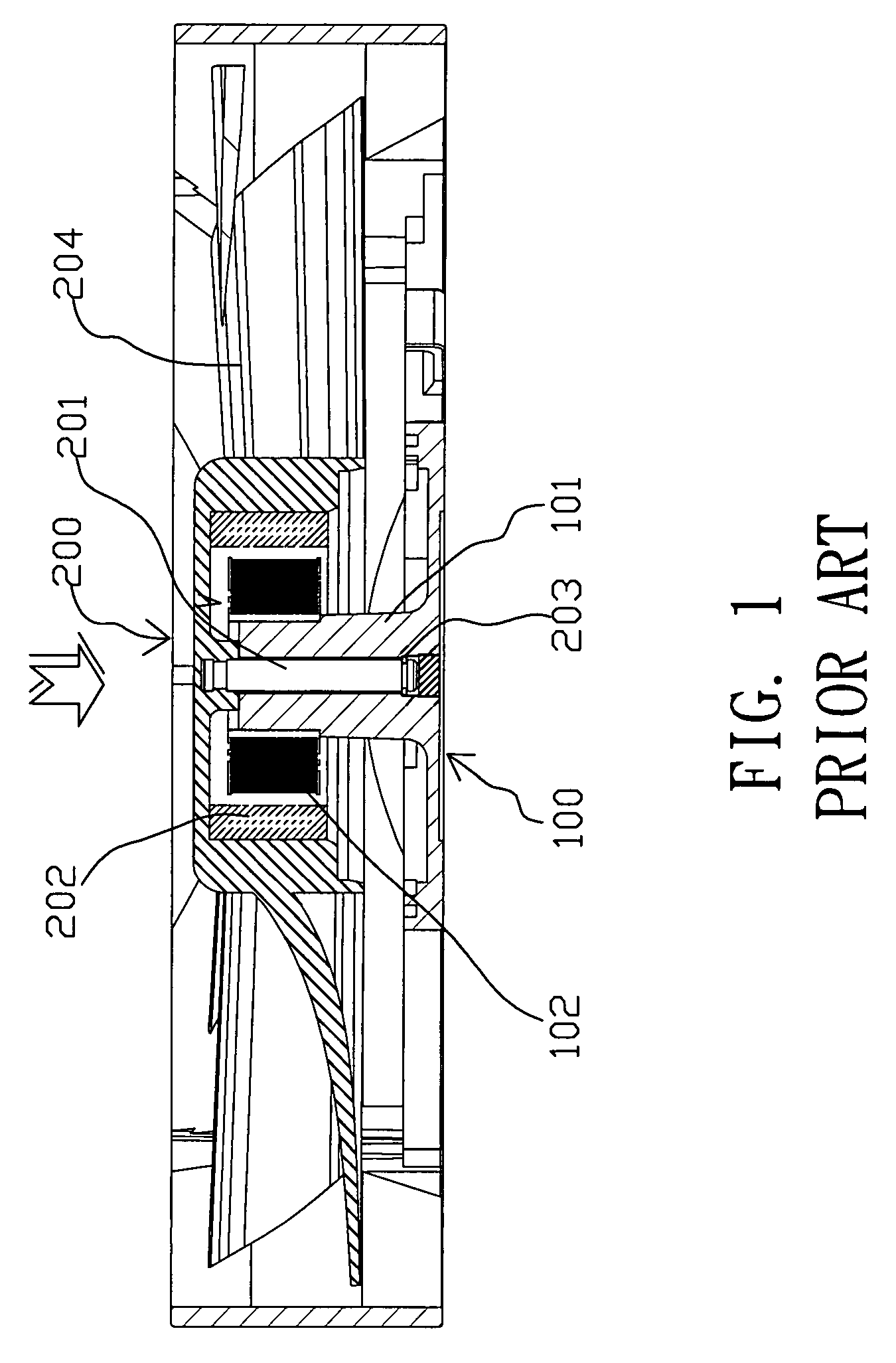
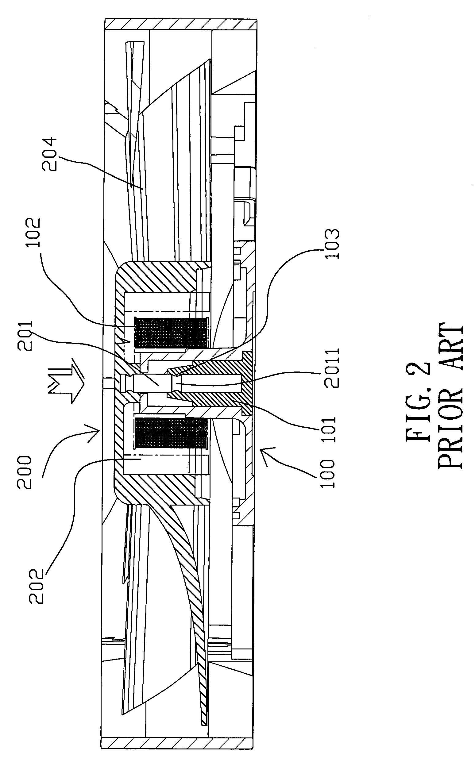
As a result, the axle 201 and bearing 101 are worn out easily after a continuous use, and the axle 201 may be shifted to cause an unstable condition and increase the noise volume.
Since the bearing 101 is made of a plastic material, therefore the problems of an internal diameter error and a rough edge may arise during the manufacturing process of the bearing 101, such as a too-large / too-small internal diameter or a shifted axle.

Method used


Image

  • Enhanced thermal deformation resisting bearing of electric motor
  • Enhanced thermal deformation resisting bearing of electric motor
  • Enhanced thermal deformation resisting bearing of electric motor

Examples


Embodiment Construction

[0020]To make it easier for our examiner to understand the technical characteristics of the invention, we use preferred embodiments together with the attached drawings for the detailed description of the invention.

[0021]Referring to FIGS. 3, 4, 4A and 5 for a preferred embodiment of the present invention, the bearing comprises a frame 10, and an opening 11 penetrating the frame 10, a stator 12 installed at the middle of the surface of the opening 11a and the periphery of the stator 12 being connected to the frame 10 by a rib 13. The stator 12 further has an axle sleeve 14 and a magnetic pole 15 disposed around the periphery of the axle sleeve 14 (as shown in FIG. 5), and the axle sleeve 14 is perpendicular to the stator 12, and the axle sleeve 14 has a hollow circular bearing 16 (wherein the axle sleeve and the bearing of this embodiment are made of a hard plastic material), and the bearing 16 has a hollow hole groove 17 disposed around the hollow hole groove 17 for dividing the bea...


PUM


Abstract

This invention discloses an enhanced thermal deformation resisting bearing of an electric motor. The bearing includes a frame for containing a stator and a rotor. The stator has an axle sleeve sheathed with a bearing. The bearing has a hole groove for dividing the bearing into inner and outer layers. A connecting portion maintains an appropriate interval between the inner and outer layers. An embedded groove is extended inward and disposed at a free end of the axle sleeve. The rotor has an axle, and the periphery of the axle has a groove. The groove corresponds with the connecting portion of the bearing. The rotor has a protruding latch disposed proximate to the axle and embedded into the embedded groove. If the axle rotates in the bearing, the thinner inner layer will be expanded by high temperature, but the thicker connecting portion still maintains the bearing in its position.

Description

BACKGROUND OF THE INVENTION[0001]1. Field of the Invention[0002]The present invention relates to an enhanced thermal deformation resisting bearing of an electric motor, and more particularly to a bearing having a connecting portion and an axle groove for maintaining the shape of the bearing and preventing a shift of an axle and an adverse effect on the operation of the axle due to expansions and deformation caused by the high temperature produced by the rotation, so as to achieve the effects of reducing noises and enhancing the life expectancy and efficiency of the electric motor.[0003]2. Description of the Related Art[0004]Referring to FIG. 1 for a heat dissipating fan of a computer in accordance with a prior art, the heat dissipating fan comprises a stator 100 and a rotor 200. The stator 100 is comprised of a stator 100 disposed at the central position of the stator 100, a hollow circular bearing 101 disposed in the stator 100, and a magnetic pole 102. The rotor 200 is comprised o...

Claims


Application Information

Patent Timeline
Patent Type & Authority Patents(United States)
IPC IPC(8): H02K5/16F16C33/02
CPCF04D29/057F04D29/5853F16C17/02F16C33/04F16C33/20H02K5/1677F04D25/062F04D25/0626
Inventor LIN, CHUN-JU
Owner TEK CHAIN TECH
Learn More