
Fuse cap for a blade fuse

a fuse and fuse cap technology, applied in the direction of coupling device details, coupling contact members, coupling device connections, etc., can solve the problems of undesired contact between exposed connections and undesired contact, and difficulty in connecting directly to the battery, so as to prolong the life of the fuse, prevent deformation, and enhance the extensible resistance of metal.

Inactive Publication Date: 2009-05-12
KS TERMINALS INC
View PDF29 Cites 6 Cited by
  • Summary
  • Abstract
  • Description
  • Claims
  • Application Information

AI Technical Summary

Benefits of technology

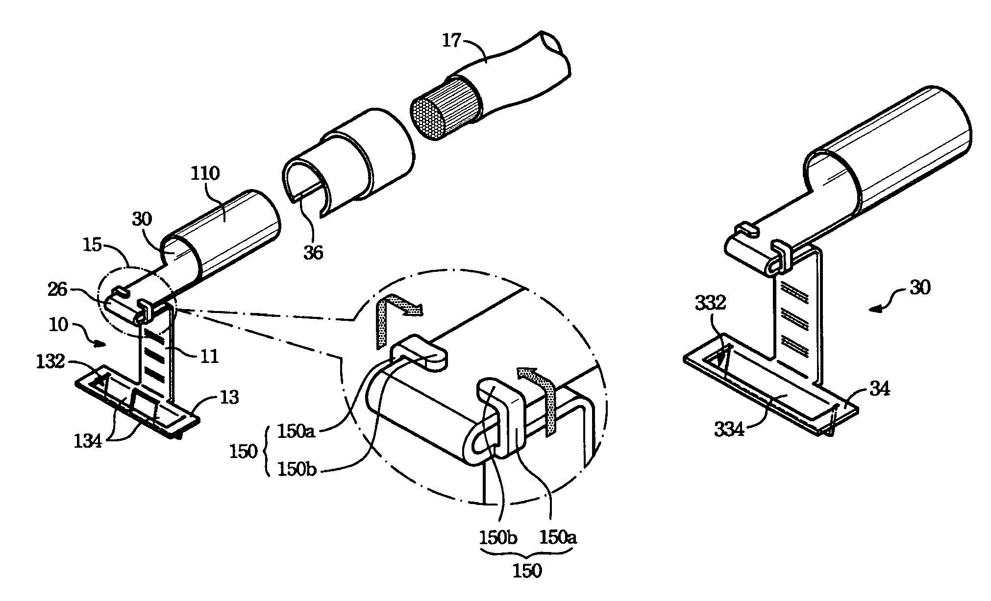
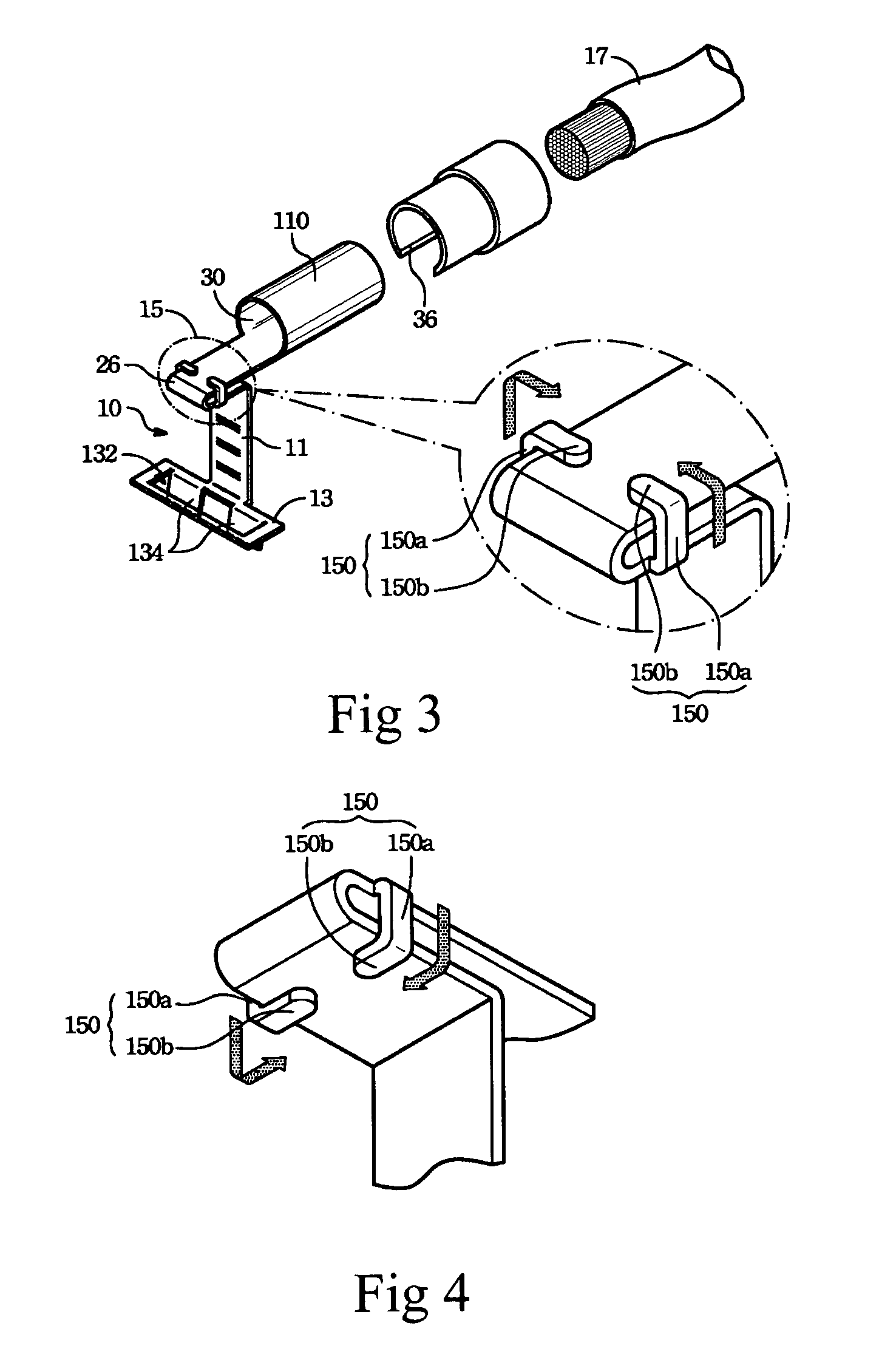
"The present invention is a blade fuse cap that includes a locking element to securely hold the fuse in place. The fuse cap is made of a single metal piece, which eliminates the need for additional parts and increases the resistance to deformation. The locking element has at least one pair of opposite or offset clamping portions that tightly secure the fuse to the cap, reducing the risk of unstable electrical connections due to automobile vibration. This design not only reduces costs but also provides better protection for the circuitry."

Problems solved by technology

In many circumstances, it is difficult to connect to the battery directly through wiring, and thus, blade fuse is commonly used in the electronic systems of automobiles.
The exposed connection may encounter undesired contact due to car vibration or oxidation of the exposed connection because there's no device to completely secure the blade fuse with the electric connector.

Method used


Image

  • Fuse cap for a blade fuse
  • Fuse cap for a blade fuse
  • Fuse cap for a blade fuse

Examples


Embodiment Construction

[0015]The present invention discloses a fuse cap structure of a blade fuse used in an automobile. The following figures are not illustrated in actual proportion and are only meant to describe the characteristics of the present invention.

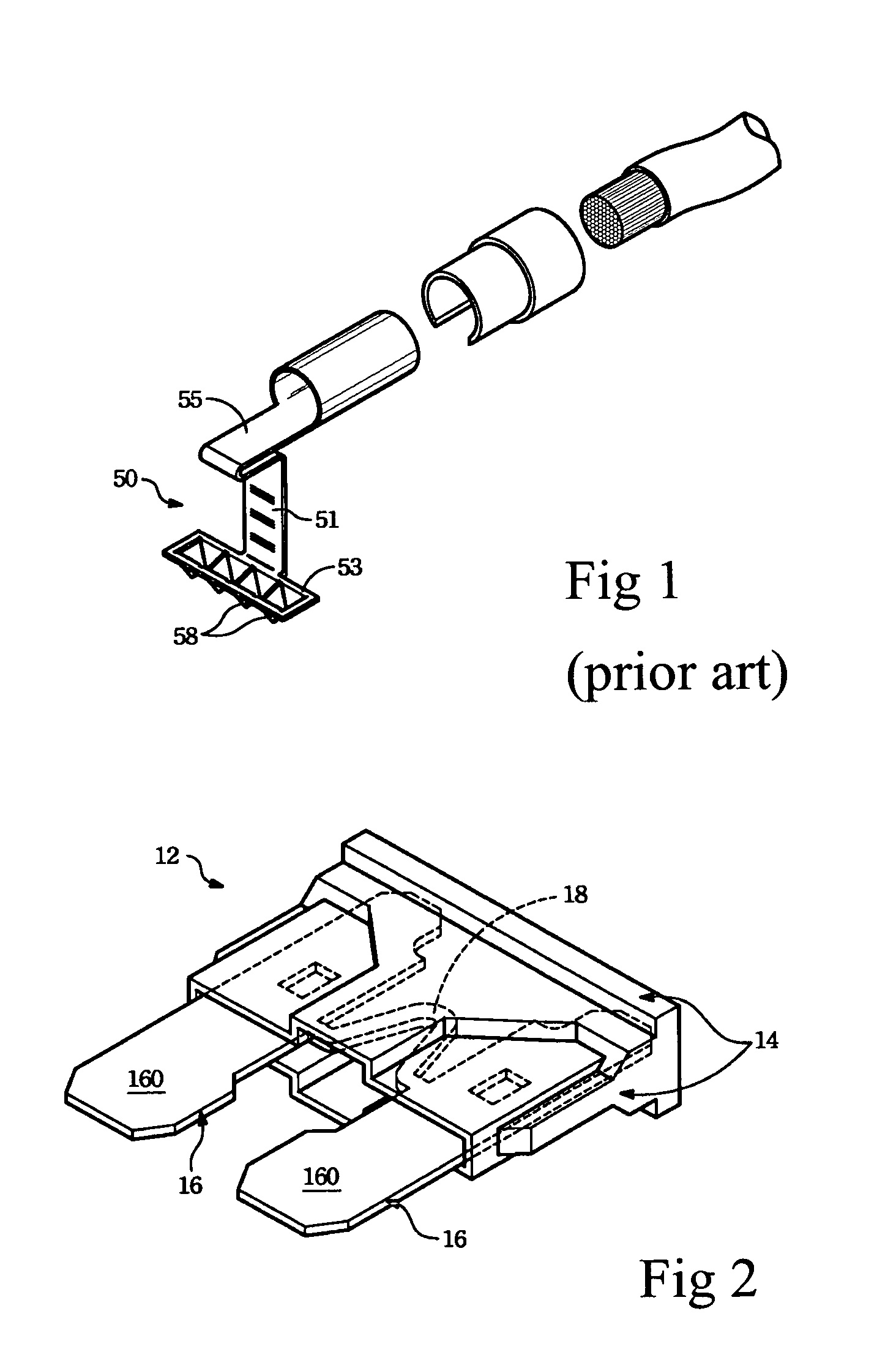
[0016]FIG. 2 illustrates the perspective view of the conventional blade fuse 12 prior to inserting the fuse cap 10 of the present invention. As shown, the blade fuse 12 is externally covered by the blade box 14, a pair of parallel arranged blades 16 is received within the blade box 14, a fuse body 18 is connected between the two blades 16; a portion of the blade 16 is extended from the blade box 14 acting as the connection160; the blade fuse 12 is a prior art and will not be described in details herein. However, the blade fuse 12 is secured in the automobile or at a predetermined position in other mobile electronic devices with at least one fuse cap 10 disclosed in each of the embodiments in accordance with the present invention so as to be electroni...


PUM


Abstract

The blade fuse comprises a fuse body, a pair of significantly parallel blades connecting the fuse body and partially extending thereof to form electric connections, and a blade box for receiving the fuse body and the parallel blades.

Description

BACKGROUND OF THE INVENTION[0001]As more and more cars are equipped with alarm systems, navigation systems and video / audio systems, consumers need to cut off the power when entering the automobile electronic system to protect the automobile circuitry. In many circumstances, it is difficult to connect to the battery directly through wiring, and thus, blade fuse is commonly used in the electronic systems of automobiles.[0002]Conventionally, a blade fuse includes a pair of parallel blades and a blade box. The blades are received within the blade box, and a portion of the blades is extended outwardly from the blade box acting as a connection. The exposed connection may encounter undesired contact due to car vibration or oxidation of the exposed connection because there's no device to completely secure the blade fuse with the electric connector. In view of the disadvantages of the conventional blade fuse, U.S. Pat. No. 5,882,229 developed a fuse cap that can provide a good electrical con...

Claims


Application Information

Patent Timeline
Patent Type & Authority Patents(United States)
IPC IPC(8): H01H85/143H01H85/165
CPCH01H85/0417H01H85/205H01H2085/206
Inventor LU, YUAN-FENG
Owner KS TERMINALS INC
Learn More