
Method and apparatus for time domain reflection test of transmission line

a transmission line and time domain technology, applied in the direction of pulse reflection methods, fault location, instruments, etc., can solve the problems of increased operating costs of operators, increased manpower and material resources, and inability to normalize the operation of xdsl services, etc., to achieve the effect of convenient and accurate measuremen

Inactive Publication Date: 2009-05-12
HUAWEI TECH CO LTD
View PDF8 Cites 20 Cited by
  • Summary
  • Abstract
  • Description
  • Claims
  • Application Information

AI Technical Summary

Benefits of technology

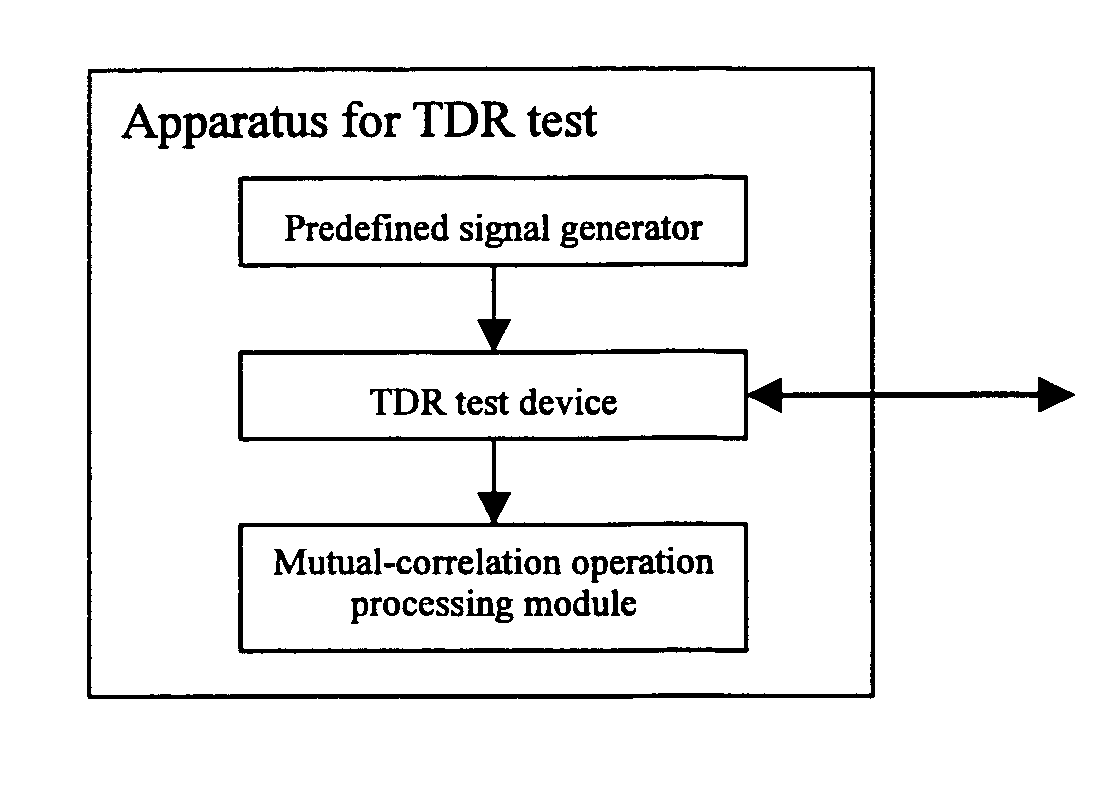
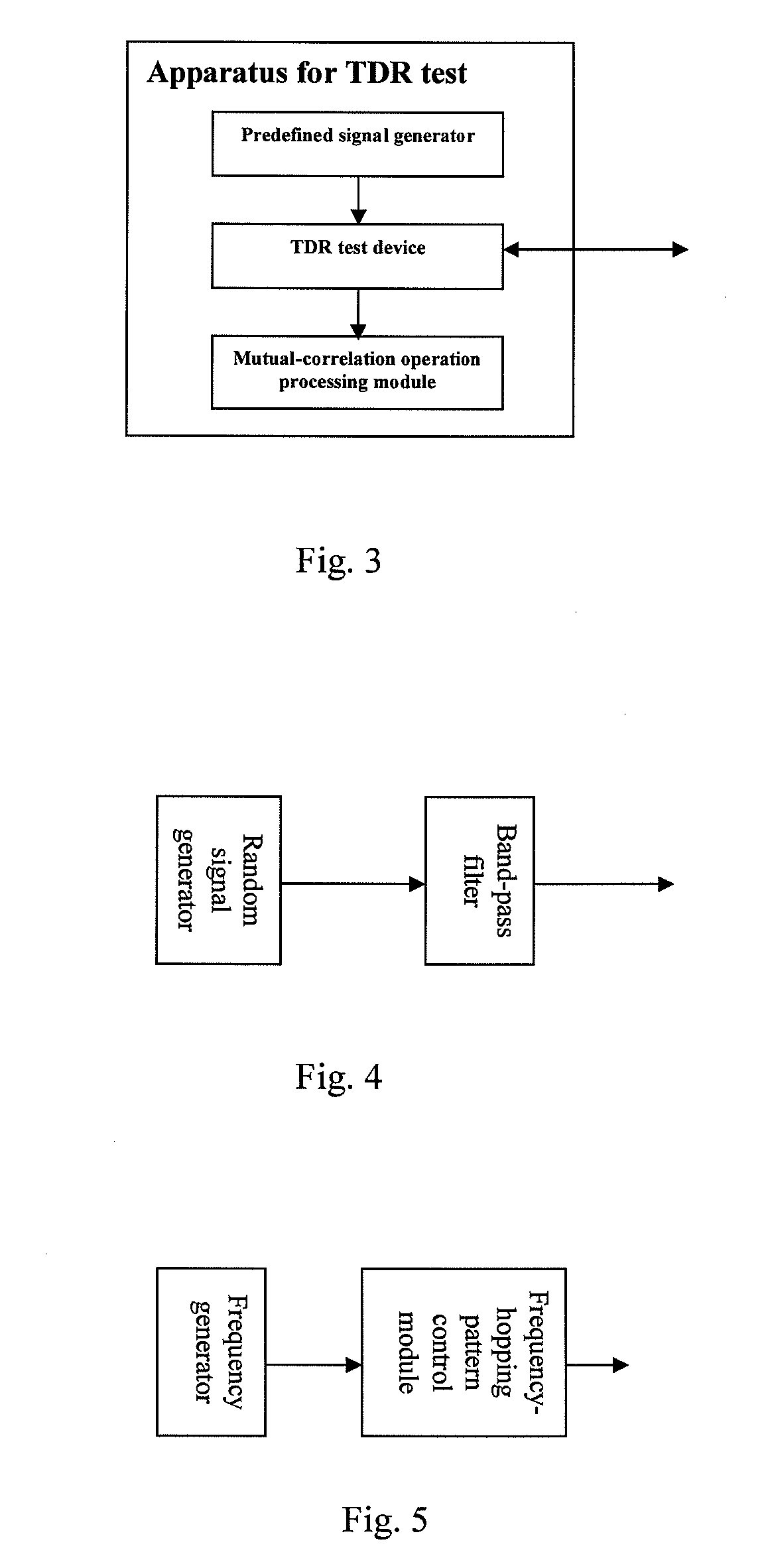
[0015]An embodiment of the present invention provides a method and an apparatus for TDR (Time Domain Reflection) test of a transmission line, so as to carry out a TDR test of the transmission line more conveniently and accurately.
[0037]It can be seen that the technical solutions of the present invention described above have the advantages of a high signal energy, a high distance resolution, and a better capability of noise resistance. Therefore, the SELT (Single-End Line Test) apparatus designed in accordance with the TDR test solution in the present invention has a good adaptability to environment, a high test accuracy, and an excellent capability of noise resistance. The method of the present invention is very useful for TDR test of large-scaled DSLAM (DSL Access Multiplexer) equipment.

Problems solved by technology

In the actual application environment, however, xDSL service can not be put into operation normally on all the twist pairs of subscribers at an office.
This process requires a great deal of manpower and material resources.
As a result, the operating cost of the operators may be increased significantly.
(1)Since the self-correlation of these waveforms is not strong, the receiving end can not distinguish correctly if there is a superimposition in the echo.
(2)If a test loop is long, the echo signal will be weak; accordingly, the signal is susceptible to interference of external signals, especially in the case of a square wave.
Thus, for the unknown lines, trial tests have to be carried out repeatedly, which will cost a long time.
(4)For a complicated test loop (e.g., when there are two bridge taps), those test signals will not function well sometimes.
(5)The line test may have adverse effects on the working xDSL lines in the same cable.

Method used


Image

  • Method and apparatus for time domain reflection test of transmission line
  • Method and apparatus for time domain reflection test of transmission line
  • Method and apparatus for time domain reflection test of transmission line

Examples


Embodiment Construction

[0049]In the embodiments of the present invention, a set of test signals, each of which has a stronger self-correlation and a weaker mutual-correlation with other signals, are selected during the TDR test process. Thus, the test accuracy may be improved.

[0050]Hereinafter, the TDR test process will be described first to facilitate further understanding of the present invention.

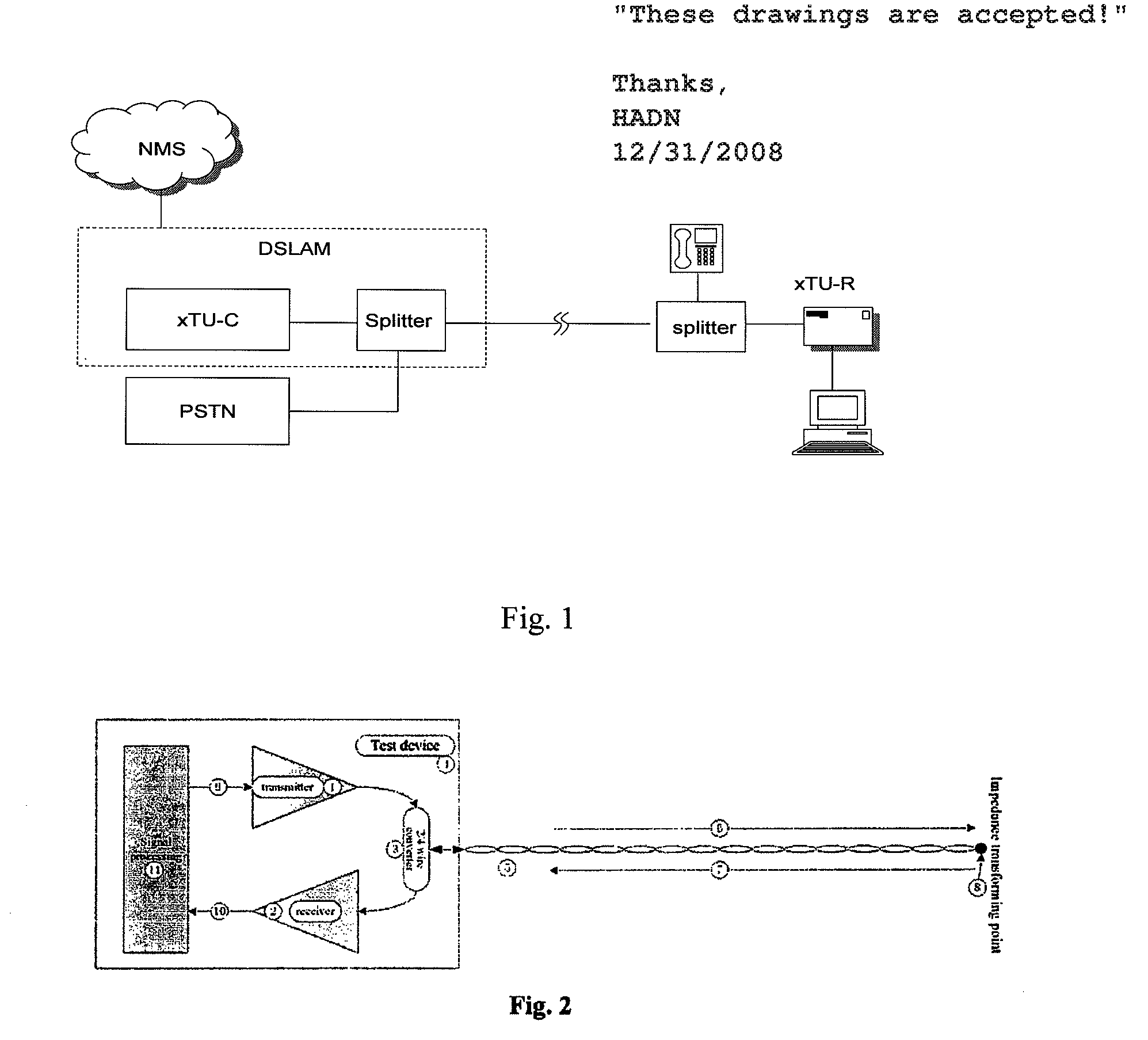
[0051]As shown in FIG. 2, in the TDR test, a transmitter 1 transmits a test signal which has been driven to a Two-Wire / Four-Wire Conversion 3, and then the test signal is driven onto a line 5. The test signal travels forward in the direction 6 and is reflected at an impedance transforming point 8. Then the signal travels in the reverse direction 7, and finally reaches a receiver 2 via the Two-Wire / Four-Wire Converter 3. In the returned signal, the reflected signal will be superimposed with the signal in the direction 6. The TDR test is to process the signal returned to the receiver 2 to obtain the test result, ...


PUM


Abstract

The present invention relates to a method and an apparatus for TDR (time domain reflection) test of a transmission line. In the method, first, a test signal meeting the test requirement of self-correlation and mutual-correlation is determined and transmitted in the transmission line, in which the test signal may be a band-limited random signal, a frequency agility signal, or a regular frequency modulation signal. Then, a TDR test is performed according to the test signal transmitted in the transmission line. The SELT (Single-End Line Test) apparatus configured in accordance with the TDR test solution in the present invention has a good adaptability to environment, a high test accuracy, and an excellent capability of noise resistance. The method of the present invention is very useful for TDR test of large-scaled DSLAM (DSL Access Multiplexer) equipments.

Description

CROSS-REFERENCE TO RELATED APPLICATIONS[0001]This application claims priority to Chinese Patent Application priority number 200510116787.9, filed Oct. 28, 2005, the disclosures of which are hereby incorporated herein by reference.FILED OF THE INVENTION[0002]The present invention relates to the communication technology field, particularly to a method and an apparatus for time domain reflection (TDR) test of a transmission line.BACKGROUND OF THE INVENTION[0003]xDSL (Digital Subscriber Line) is a technique for high-speed data transmission through Unshielded Twist Pair (UTP). In addition to the base-band transmission DSLs, such as IDSL and SHDSL, the pass-band transmission xDSL utilizes the frequency division multiplexing (FDM) technique so that the xDSL service may coexist with the POTS (Plain Old Telephone Service) in a same twist pair. The xDSL service occupies the higher frequency band, while the POTS occupies the base band below 4 KHz. The POTS signal and the xDSL signal may be sep...

Claims


Application Information

Patent Timeline
Patent Type & Authority Patents(United States)
IPC IPC(8): G01R31/11
CPCG01R31/11H04M3/28
Inventor SHI, QINGQUAN
Owner HUAWEI TECH CO LTD
Learn More