
Packaging case for wiper blades

a technology for wiper blades and packaging cases, applied in the field of packaging cases for automotive wiper blades, can solve the problems of increasing manufacturing costs and occupying too much space in the case when loaded, and achieve the effect of reducing manufacturing costs

Inactive Publication Date: 2009-05-05
PARK LTD
View PDF6 Cites 51 Cited by
  • Summary
  • Abstract
  • Description
  • Claims
  • Application Information

AI Technical Summary

Benefits of technology

[0008]The present invention is designed to solve the problems of the prior art, and therefore an object of the invention is to provide a wiper blade packaging case capable of reducing manufacturing cost by being manufactured in a single case and packaging a wiper blade without distorting its shape.
[0009]In order to accomplish the above objects of reducing manufacturing cost by forming a case in one piece and preventing deformation of wiper blades, the present invention provides an automotive wiper blade packaging case including: a lower case having a wiper storage compartment opened upward and concaving downward; a locating plate connected along the length of one edge of the lower case by a film hinge, to be disposed in the upper portion of the storage compartment, and having two linearly arranged rows of pluralities of locating tabs with a space therebetween for inserting a wiper blade; and an upper case connected along the length of another edge of the lower case by a film hinge, and having a storage compartment opened upward and a plurality of locking protrusions around a perimeter thereof for coupling with the lower case, wherein the lower case, the locating plate, and the upper case are formed in one piece of a transparent synthetic resin.

Problems solved by technology

Because the widths of such cases are inappropriately broad in comparison to the lengths, the case takes up too much space when loaded for transport or arranged for display.
Because the two cases must be manufactured separately, which requires additional manufacturing processes and materials, the manufacturing cost increases.

Method used


Image

  • Packaging case for wiper blades
  • Packaging case for wiper blades
  • Packaging case for wiper blades

Examples


Embodiment Construction

[0017]Hereinafter, a preferred embodiment of the present invention will be described in detail with reference to the accompanying drawings.

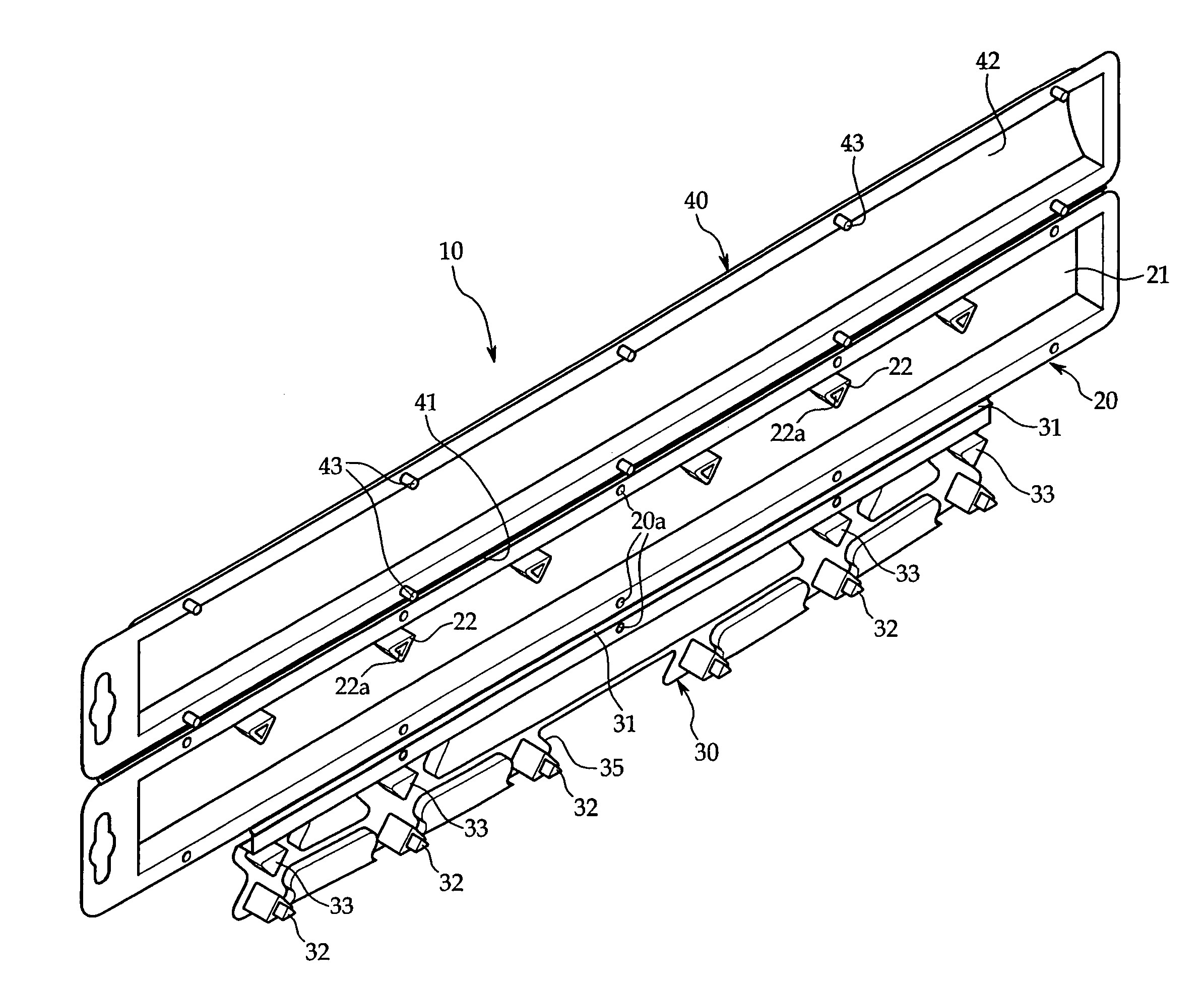
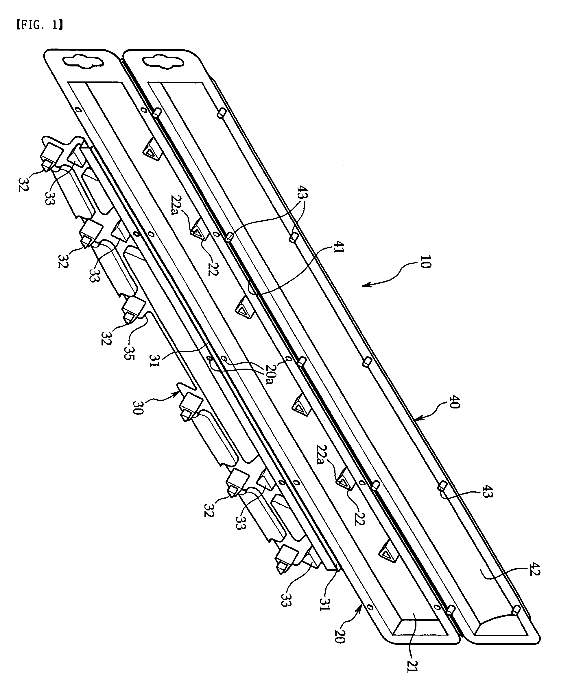
[0018]FIG. 1 is a perspective view of a wiper blade packaging case according to the present invention, FIG. 2 is a sectional view of FIG. 1, FIG. 3 is an exemplary view showing a wiper blade placed in a wiper blade packaging case according to the present invention, and FIG. 4 is a sectional view showing an assembled wiper blade packaging case according to the present invention.

[0019]Referring to FIGS. 1 and 2, the wiper case 10 is formed in one piece of a transparent synthetic resin.

[0020]The automotive wiper case 10 includes a lower case 20, a locating plate 30 connected along the length of one edge of the lower case 20 by a film hinge 31, and an upper case 40 connected along the length of the other edge of the lower case 20 by a film hinge 41.

[0021]Here, the locating plate 30 for enclosing and perpendicularly straightening a wiper blade 5, is s...


PUM

PropertyMeasurementUnit
transparentaaaaaaaaaa
lengthaaaaaaaaaa
curvaturesaaaaaaaaaa

Abstract

A packaging case for wiper blades includes a lower case (20), a locating plate (30), and an upper case (40). The lower case (20) has a wiper storage compartment (21) opened upward and recessed downward. The locating plate (30) is attached via a hinge (31) on an edge of the lower case (20) to reside in an upper portion of the storage compartment (21), and has two rows of pluralities of locating tabs (32, 33), between which a space for inserting a wiper blade (5) is allocated. The upper case (40) is attached via a hinge (41) on another edge of the lower case (20), and has a plurality of locking protrusions (43) on the periphery at the upper portion of the storage compartment (42) for coupling to the lower case (20). The lower case (20), locating plate (30), and upper plate (40) are formed in one piece.

Description

BACKGROUND OF THE INVENTION[0001]1. Field of the Invention[0002]The present invention relates to a packaging case for automotive wiper blades, and more particularly, to a packaging case for automotive wiper blades that prevents deformation of wiper blades during storage, while reducing packaging volume and space required for transport and display, and is, at the same time, inexpensive to manufacture.[0003]2. Description of the Related Art[0004]Automotive wiper blades are instruments for clearing droplets of rain, dust, or other foreign objects from the front (and rear) windshield of a vehicle. As parts that require replacement due to wear after a certain duration of use, wiper blades are packaged in cases to transport, display, and vend them.[0005]Because vehicular windshields have curved surfaces, automotive wiper blades are curved as well. Thus, wiper blade packaging cases of the prior art are formed in curved or straight designs according to the curvatures of the blades they are ...

Claims


Application Information

Patent Timeline
Patent Type & Authority Patents(United States)
IPC IPC(8): B65D73/00
CPCB65D25/10B65D75/22B65D2585/6882B65D2585/6885B60S2001/3898B07C1/02
Inventor PARK, SE-HEON
Owner PARK LTD
Learn More