
Method for determining a minority carrier diffusion length using surface photo voltage measurements

a surface photo voltage and minority carrier technology, applied in the field of semiconductor materials, can solve the problems of inability to measure the carrier concentration n directly, the parameter a and s are not stable, and the contamination of the carrier is not easy to d

Active Publication Date: 2009-04-21
SUMCO CORP
View PDF8 Cites 2 Cited by
  • Summary
  • Abstract
  • Description
  • Claims
  • Application Information

AI Technical Summary

Benefits of technology

[0030]In view of the foregoing, a non-limiting feature of the present invention provides an accurate method of determining the minority carrier diffusion length of a material.
[0031]Another non-limiting feature of the present invention is that it reduces measurement errors due to the non-linear V-N-relationship, reduces measurement errors due to the time and light exposure dependency of the V-N-relationship and eliminates the need for time-consuming intensity adjustments at each measurement site.
[0032]Another non-limiting feature of the present invention is that it does not require major hardware modification to existing tools.

Problems solved by technology

When a semiconductor material is processed, it may become contaminated, during one or more processing steps, by a heavy metal, such as iron, for example.
However, the carrier concentration N cannot be measured directly.
However, the parameters A and S are not stable values.
Unfortunately, illuminating the material with a measurement light can change these parameters.
However, a flaw of the Constant Voltage Approach is that the adjustment of the photon flux of the second excitation light required by the approach results in a relatively long measurement time.
Since the parameters A and S are time dependent, they may change between the measurements of I1 and I2, which results in significant measurement errors.
Unfortunately, voltages are practically immeasurable at such a low excitation.
However, under practical conditions the non-linearity does change under the influence of the measurement light and is different at different measurement sites, causing significant measurement errors.
Thus, the Linear Constant Flux Approach suffers from non-linearity errors in addition to errors resulting from the V-N-relation changes between switching light sources.
This method solves the problem of the changing V-N-relation in time, however, it complicates the non-linearity problem by superimposing several differently modulated photon fluxes.
Unfortunately, this will worsen the non-linearity measurement error.
In addition, it will enhance measurement artifacts caused by the time dependency of the V-N-relation under light exposure.
In addition, by using different modulation frequencies, this method is very likely susceptible to phase shift-frequency dependencies, leading to previously non-existing problems.
Thereby, this method avoids enhanced non-linearity error as well as the phase-shift error of the method described in U.S. Pat. No. 6,512,384, but still suffers from the same level of non-linearity error as the Linear Constant Flux Approach.
Unlike the Constant Voltage Approach, this method is completely insensitive to V-N-relation details, since it does not even measure individual voltages.
Like the Constant Voltage Approach, this method also involves a time-consuming adjustment of intensities at each measurement site and is therefore potentially slower than methods that work with fixed intensities and only rely on voltage measurements.

Method used


Image

  • Method for determining a minority carrier diffusion length using surface photo voltage measurements
  • Method for determining a minority carrier diffusion length using surface photo voltage measurements
  • Method for determining a minority carrier diffusion length using surface photo voltage measurements

Examples


Embodiment Construction

[0056]The particulars shown herein are by way of example and for purposes of illustrative discussion of the embodiments of the present invention only and are presented in the cause of providing what is believed to be the most useful and readily understood description of the principles and conceptual aspects of the present invention.

[0057]One premise of the present invention is that equation (7) can be rewritten as:

L=(d2−d1CR) / (CR−1),   (9)

where C=I2 / I1 and R=N1 / N2. Further, if N1 is referred to as Nref0 and I1 is referred to as Iref0, then R can be expressed as R=Nref0 / N2 and C can be expressed as C=I2 / Iref0.

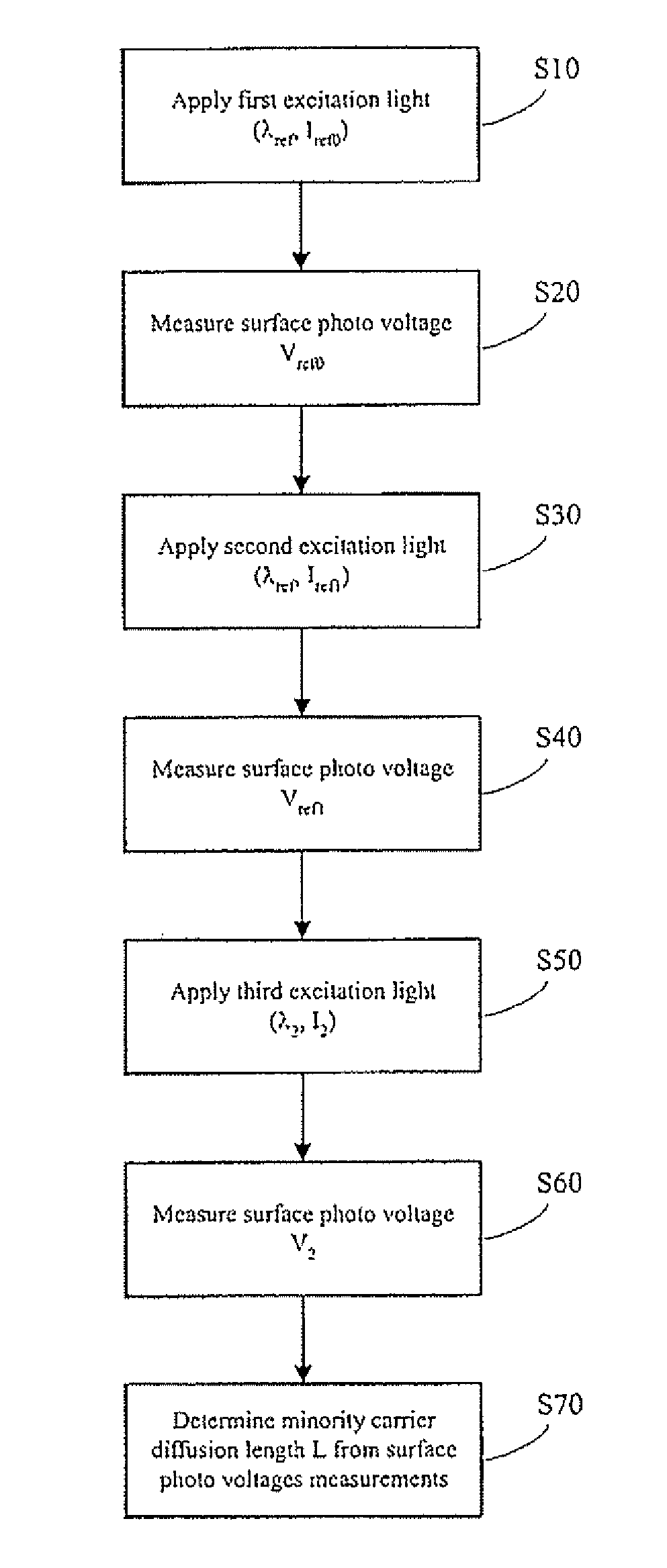
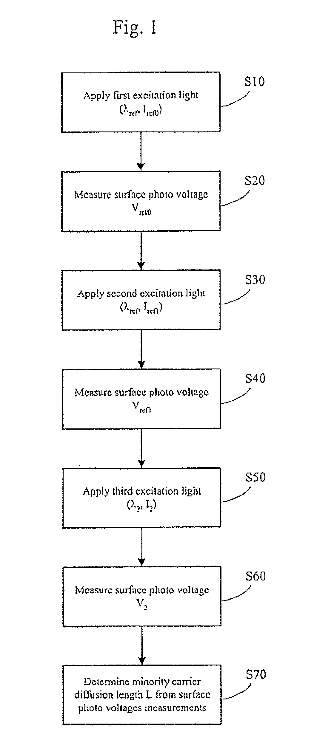
[0058]A process of determining the minority carrier diffusion length L of a material is described below with reference to the flowchart shown in FIG. 1.

[0059]First, a first excitation light having a reference wavelength λref and a first photon flux Iref0 is applied to a subject material (step S10), generating a carrier concentration Nref0, and a resulting surface photo voltage V...


PUM

PropertyMeasurementUnit
diffusion lengthaaaaaaaaaa
first photon fluxaaaaaaaaaa
first wavelengthaaaaaaaaaa

Abstract

A method of determining a diffusion length of a minority carrier in a material which includes applying a first excitation light having a first photon flux to a material, measuring a first surface photo voltage resulting from the application of the first excitation light, applying a second excitation light having a second photon flux to the material, measuring a second surface photo voltage resulting from the application of the second excitation light, applying a third excitation light having a third photon flux, having a predetermined ratio to the first photon flux, to the material, measuring a third surface photo voltage resulting from the application of the third excitation light, determining a diffusion length of a minority carrier in the material based on the measured first, second and third surface photo voltages.

Description

BACKGROUND OF THE INVENTION[0001]1. Field of the Invention[0002]The present invention relates to semiconductor materials and, more particularly, to determining a diffusion length of a minority carrier in a semiconductor material.[0003]2. Description of Related Art[0004]When a semiconductor material is processed, it may become contaminated, during one or more processing steps, by a heavy metal, such as iron, for example. Such contamination degrades the semiconductor material, as the contaminants act as recombination centers which eliminate charge carriers in the semiconductor material.[0005]Commonly, contaminants are detected by determining a minority carrier diffusion length of a semiconductor material, which is the distance a minority carrier moves during its lifetime.[0006]To determine a minority carrier diffusion length in a material, minority carriers can be generated in the material by applying an excitation light, such as a laser, to a surface of the material. The number of mi...

Claims


Application Information

Patent Timeline
Patent Type & Authority Patents(United States)
IPC IPC(8): G01R31/26G01N21/47G01R31/00
CPCG01R31/2656G01R31/2648
Inventor ORSCHEL, BENNOBUCZKOWSKI, ANDRZEJKIRSCHT, FRITZ
Owner SUMCO CORP
Learn More