Equipment for moving the roll of a paper machine

a paper machine and roll technology, applied in the field of equipment for moving the roll of a paper machine, can solve the problems of large forces in the foundations of the paper machine, unsuitable simple operating devices such as hydraulic cylinders, complicated equipment, etc., and achieve the effect of simple control devices, accurate adjustment, and cost-effective equipmen

Inactive Publication Date: 2009-04-21
VALMET TECH INC
View PDF10 Cites 10 Cited by
  • Summary
  • Abstract
  • Description
  • Claims
  • Application Information

AI Technical Summary

Benefits of technology

[0015]The invention is intended to create an entirely new type of equipment for moving a roll in a paper machine, which is simpler, more reliable, and cheaper than previously and by means of which the drawbacks of the prior art can be avoided. In the equipment according to the invention, particularly the drive train and its control are implemented in a new and surprising manner. The pairs of masses can be rotated using a single motor, by using a special drive train, which permits the mainly mechanical implementation of the phase-difference adjustment. The simple and small drive train can even be combined with existing equipment, without having to alter the pairs of masses or the cradle. Further, in the equipment, the control of the motor and of the drive train can be implemented separately. Thus, for example, the stroke achieved by the equipment can be adjusted independently of the motor. In addition, though the devices required for the control are simple, the adjustment is nevertheless precise. The total cost of the equipment according to the invention is considerably lower than that of the prior art. In addition to this, control of the equipment is ensured even in fault situations, thus eliminating, or at least substantially reducing the danger of breakage. The equipment is also smaller in size and easier to install than before.

Problems solved by technology

On account of the magnitude of the mass being moved and the frequency used, simple operating devices, such as hydraulic cylinders, are unsuitable for this purpose.
In addition, the use of hydraulic cylinders would induce large forces in the foundations of the paper machine.
Thus, the equipment becomes complicated and expensive, especially in the case of the automation and the electric motors.
If the electric motors, or their controls fail, or if there is a sudden total power outage, the rotational velocities of the pairs of masses decrease uncontrollably.
When returning to the critical speed range, the stroke of the apparatus will then peak suddenly, breaking the equipment and possibly even the structures of the paper machine.
The device disclosed is complicated and the forces it creates are too small to move a breast roll.
In addition, the drive train of the device cannot be adapted to the pairs of masses presently in use.
In terms of control, the gear train is also slow and also unsuitable in practice, due, among other things, to the irreversible control.

Method used


Image

  • Equipment for moving the roll of a paper machine
  • Equipment for moving the roll of a paper machine
  • Equipment for moving the roll of a paper machine

Examples


Embodiment Construction

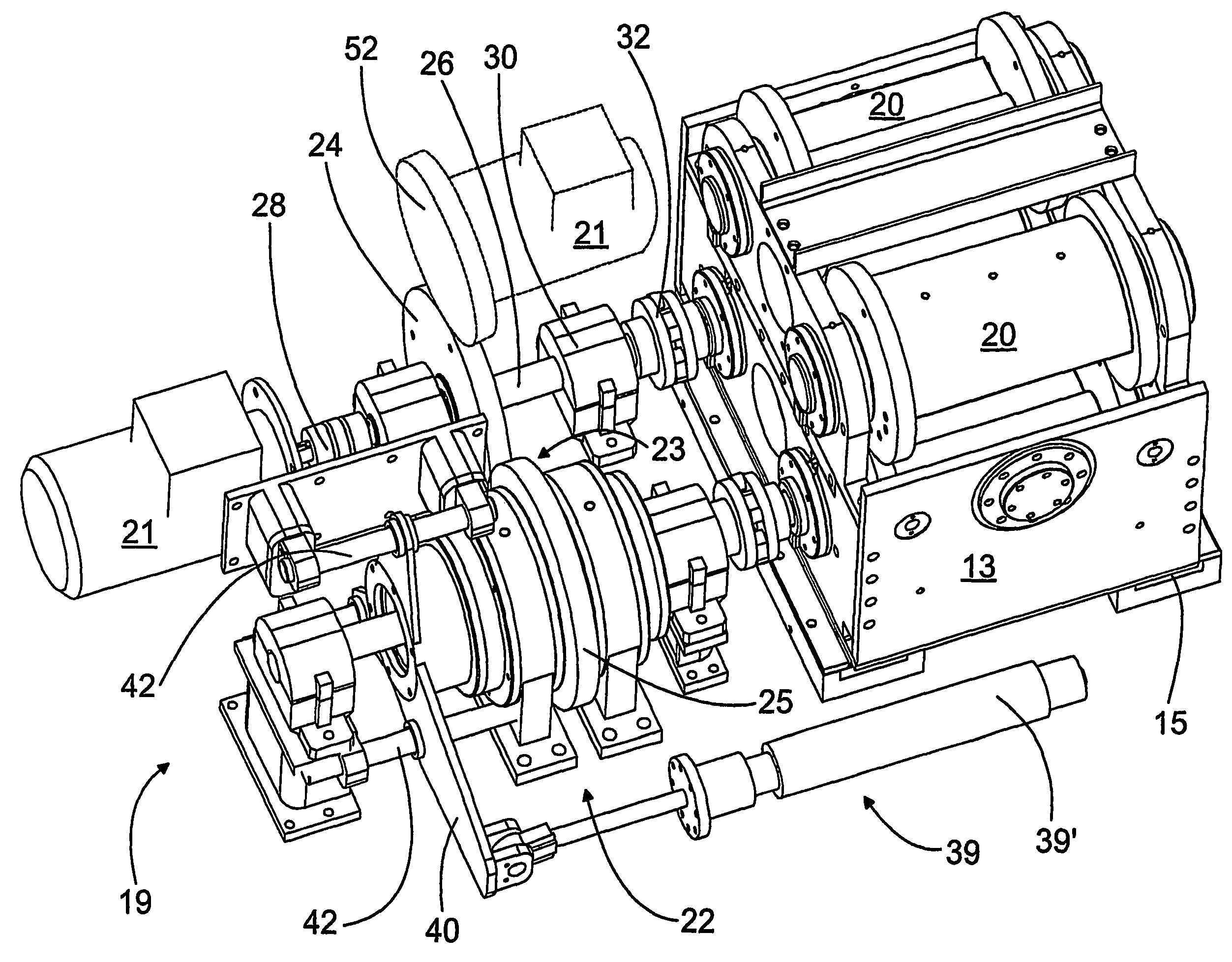
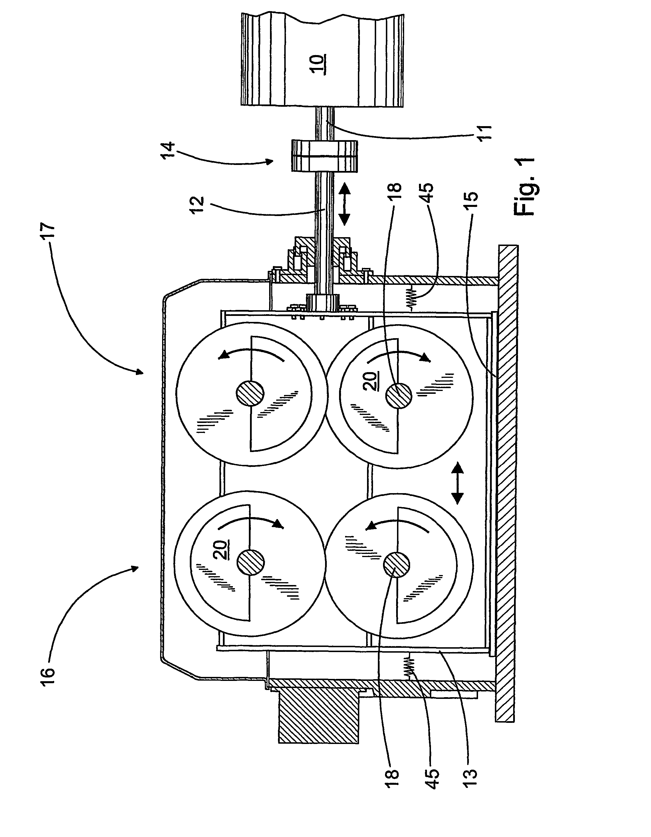
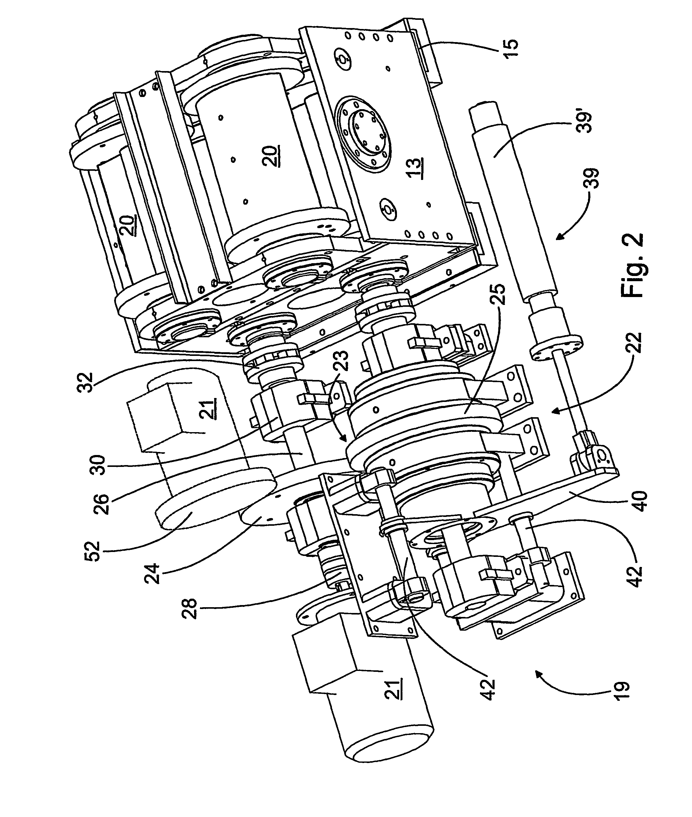
[0025]FIG. 1 shows a cross-section of the breast roll 10 of a paper machine and the equipment according to the invention attached to it. The breast roll, more simply the roll 10 is mounted at both ends in bearings, which permit the roll 10 to move axially. The axial movement usually used is about 10-30 mm. In addition, the roll 10 is connected, by a operating rod 12, to a cradle 13 forming part of the equipment. In the operating rod 12, there is additionally a thrust bearing 14, to permit the rotation of the roll 10. In other words, the operating rod 12 remains stationary, while the shaft 11 rotates. Correspondingly, the cradle 13 intended to be connected to the roll 10 is mounted in sliding bearings in the frame of the equipment. Usually, hydrostatic sliding bearings 15 are used. In other words, the cradle slides on top of a lubricant membrane. The parts of the equipment that move along with the roll 10 are thus not only the operating rod 12, but also the cradle 13 with its pairs o...


PUM


Abstract

Equipment for moving a roll in a paper machine has a movable cradle (13) for attachment to a roll (10). Two pairs of masses (16, 17) are supported rotatably on the cradle (13), in each of which there is an own drive shaft (18) for rotating the pairs of masses (16, 17). Drive devices (19) include a motor (21) and drive-train means (22). The drive-train means (22) include a pair of gears (23), which are arranged in connection with the drive shafts (18), for rotating the drive shafts (18) using a single motor (21). The drive-train means (22) also includes an adjustment element (33) for creating and adjusting the phase difference of the drive shafts (18). The adjustment element (33) is arranged between a gear (25) and the corresponding drive shaft (18), to change their position and thus to create and adjust a phase difference between the drive shafts (18).

Description

CROSS REFERENCES TO RELATED APPLICATIONS[0001]This application is a U.S. national stage application of international App. No. PCT / FI2004 / 050187, filed Dec. 15, 2004, the disclosure of which is incorporated by reference herein, and claims priority on Finnish App. No. 20035242, filed Dec. 18, 2003.STATEMENT AS TO RIGHTS TO INVENTIONS MADE UNDER FEDERALLY SPONSORED RESEARCH AND DEVELOPMENT[0002]Not applicable.BACKGROUND OF THE INVENTION[0003]The present invention relates to equipment for moving the roll of a paper machine, which roll is arranged to be moved in an axial direction, and which equipment includes[0004]a cradle arranged to move, which is intended to be attached to the roll,[0005]two pairs of masses, which are supported rotatably on the cradle,[0006]a drive shaft in each of the pairs of masses, for rotating the pairs of masses,[0007]drive devices for rotating the drive shafts in the desired phase, which drive devices include a motor and drive-train means fitted to the drive s...

Claims


Application Information

Patent Timeline
Patent Type & Authority Patents(United States)
IPC IPC(8): D21F1/18B06B1/16D21F1/20
CPCD21F1/20Y10T74/18344
Inventor HONKANEN, TAPANIJUVAKKA, TUOMOKUKKO, TIMO
Owner VALMET TECH INC
Why Eureka
Try Eureka