
Ink droplet ejection device

a technology of ejection device and droplet, which is applied in the direction of printing, other printing devices, etc., can solve problems such as the risk of malfunction

Inactive Publication Date: 2009-04-21
BROTHER KOGYO KK
View PDF8 Cites 2 Cited by
  • Summary
  • Abstract
  • Description
  • Claims
  • Application Information

AI Technical Summary

Benefits of technology

The invention is an ink droplet ejection device that prevents the ejection of minute ink droplets that can form problematic ink mists. The device includes a controller that produces control signals for ejecting ink droplets. The control signals have different pulse trains for ejecting ink droplets of different sizes. The pulse trains are designed to have lower ejection velocities for the single ink droplets than the plurality of ink droplets forming the composite dot, which prevents excessive ejection velocity and the formation of ink mists. This arrangement helps to prevent the ejection of minute ink droplets and avoid contamination.

Problems solved by technology

However, due to the above-described construction of the cavity unit in which the ink is distributed from the common chamber into the plurality of pressure chambers, when an ejection pressure is applied to at least one of the pressure chambers, the ejection pressure could be propagated to the other pressure chambers via the common chamber, thereby causing a so-called cross talk between the adjacent pressure chambers and inducing an ink ejection from the other pressure chambers.
The floating ink mists could stick inside an image forming apparatus incorporating therein a recording head, thereby causing a risk of malfunction in various operations performed by the image forming apparatus.

Method used


Image

  • Ink droplet ejection device
  • Ink droplet ejection device
  • Ink droplet ejection device

Examples


Embodiment Construction

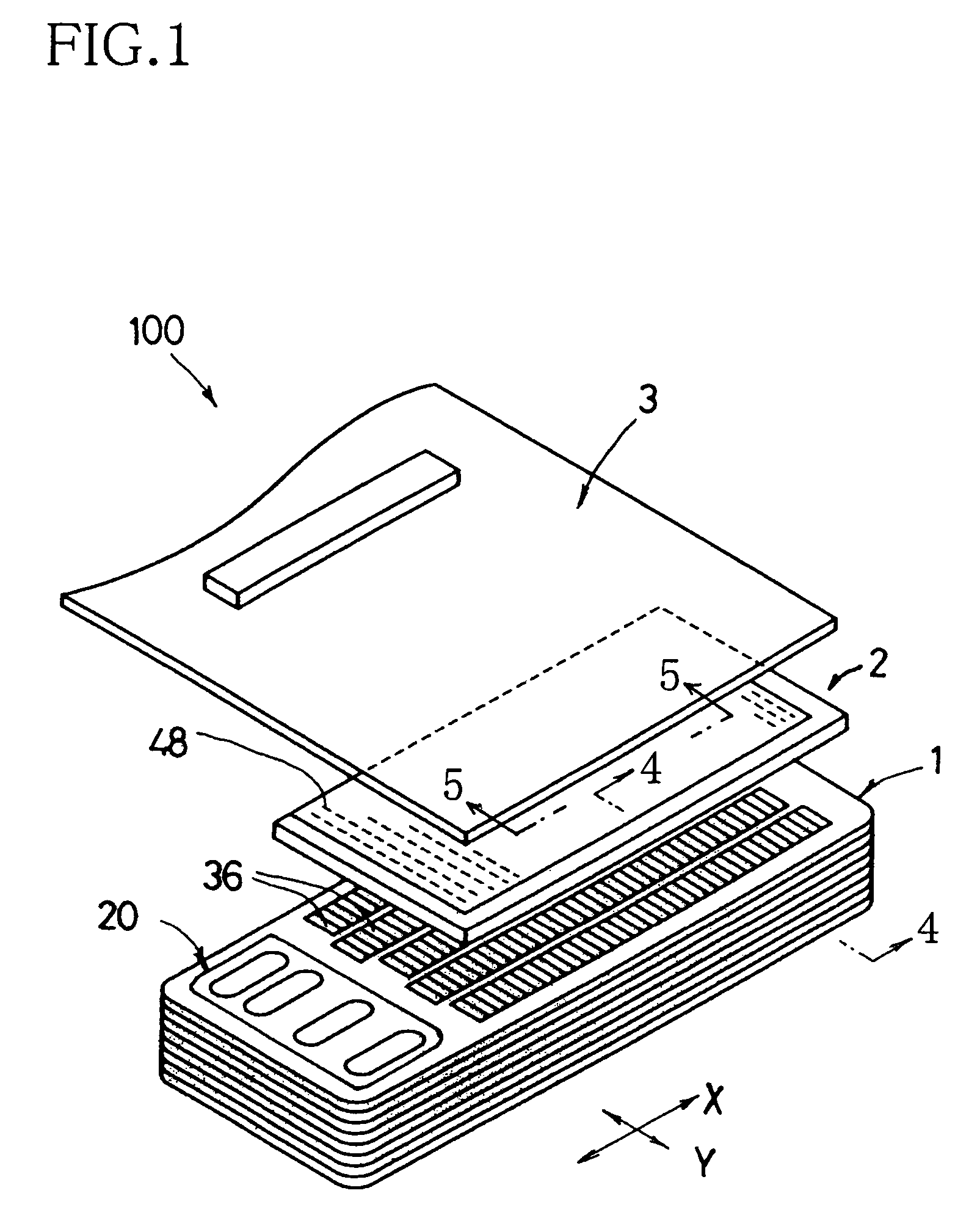
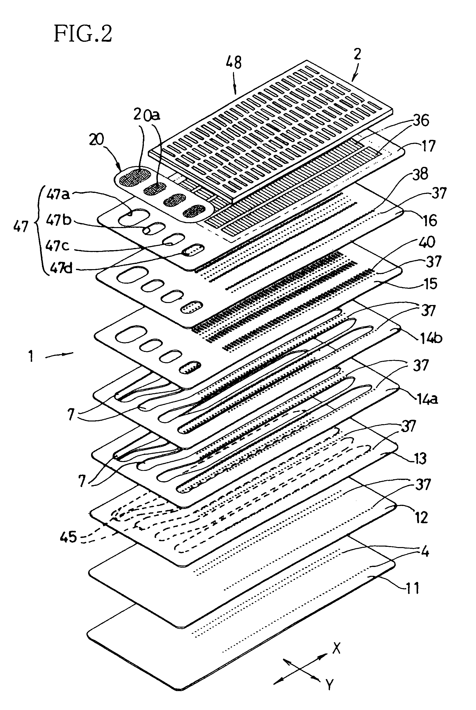
[0027]The present invention is applicable to an ink droplet ejection device such as a recording head (hereinafter referred to as “inkjet head”) 100, as shown in FIG. 1, which is constructed according to the invention. This inkjet head 100 is to be mounted on a carriage (not shown) of an inkjet printer, which is arranged to be reciprocably movable in a main scanning direction that is perpendicular to a sub-scanning direction in which a recording medium is to be fed. The inkjet printer is equipped with ink cartages (not shown) that are removably mounted on the carriage or disposed on a stationary portion of the printer, such that each of inks of four colors (e.g., black, cyan, yellow and magenta) stored in the respective ink cartridges can be supplied directly or through supplying pipes to the inkjet head 100. It is noted that, in the following description, the main scanning direction is referred also to as “second direction” or “X direction” while the sub-scanning direction is referr...


PUM


Abstract

An ink droplet ejection device including: (a) actuators each operable to apply an ejection pressure to an ink stored in a corresponding pressure chamber, for causing an ink ejection through a corresponding nozzle, whereby an image formed as a result of the ink ejection is produced on a medium; and (b) a controller supplying a control signal to each actuator, and including (b-1) a portion operable to incorporate a composite-dot forming pulse train into the control signal, for causing successive ejection of a plurality of ink droplets that cooperate to form a composite dot of the image, and (c) a portion operable to incorporate a non-composite-dot forming pulse train into the control signal, for causing an ejection of a single ink droplet that forms a non-composite dot of the image. The composite-dot forming pulse train and non-composite-dot forming pulse train have respective waveforms configured such that an ejection velocity of the single ink droplet forming the non-composite dot is lower than an ejection velocity of said plurality of ink droplets cooperating to form the composite dot.

Description

[0001]This application is based on Japanese Patent Application No. 2005-045506 filed in Feb. 22, 2005, the content of which is incorporated hereinto by reference.BACKGROUND OF THE INVENTION[0002]1. Field of the Invention[0003]The present invention relates to an ink droplet ejection device.[0004]2. Discussion of Related Art[0005]As an ink droplet ejection device, there is known a recording head that is to be incorporated in an inkjet printer. U.S. Pat. No. 6,663,208 (corresponding to JP-2002-160362A) discloses such a recording head including: (a) a cavity unit having (a-1) a plurality of nozzles located in its front portion, (a-2) a plurality of pressure chambers located in its rear portion and held in communication with the respective nozzles, and (a-3) a common ink chamber held in communication with the pressure chambers so as to distribute an ink supplied from an ink source, into the pressure chambers; and (b) a piezoelectric actuator unit fixedly disposed on the rear portion of t...

Claims


Application Information

Patent Timeline
Patent Type & Authority Patents(United States)
IPC IPC(8): B41J29/38B41J2/045
CPCB41J2/04581B41J2/04588B41J2/04593
Inventor IRIGUCHI, AKIRA
Owner BROTHER KOGYO KK
Learn More