
Micro-electromechanical structure with self-compensation of the thermal drifts caused by thermomechanical stress

a micro-electromechanical and stress-induced technology, applied in acceleration measurement, measurement devices, instruments, etc., can solve problems such as measurement errors and drifts, alterations in the performance of sensors, and the proper operation of micro-electromechanical structures. to achieve the effect of compensating thermal drifts

Active Publication Date: 2009-04-21
STMICROELECTRONICS SRL
View PDF14 Cites 25 Cited by
  • Summary
  • Abstract
  • Description
  • Claims
  • Application Information

AI Technical Summary

Benefits of technology

This solution provides intrinsic thermal compensation, eliminating measurement drifts while maintaining sensitivity, reducing the need for complex calibration and additional components, and enhancing temperature stability for precise applications like inclinometers.

Problems solved by technology

The presence of residual stress leads to considerable problems for the proper operation of micro-electromechanical structures, in particular of micro-electromechanical sensors.
This leads to alterations in the performance of the sensors, in particular measurement errors and drifts, which are moreover variable according to the production lot and at times also among sensors belonging to a same production lot.
This solution proves particularly burdensome in so far as it calls for costly and delicate measurement procedures to obtain compensation curves that accurately map the thermal drifts of the sensors, as well as appropriate compensation operations.

Method used


Image

  • Micro-electromechanical structure with self-compensation of the thermal drifts caused by thermomechanical stress
  • Micro-electromechanical structure with self-compensation of the thermal drifts caused by thermomechanical stress
  • Micro-electromechanical structure with self-compensation of the thermal drifts caused by thermomechanical stress

Examples


first embodiment

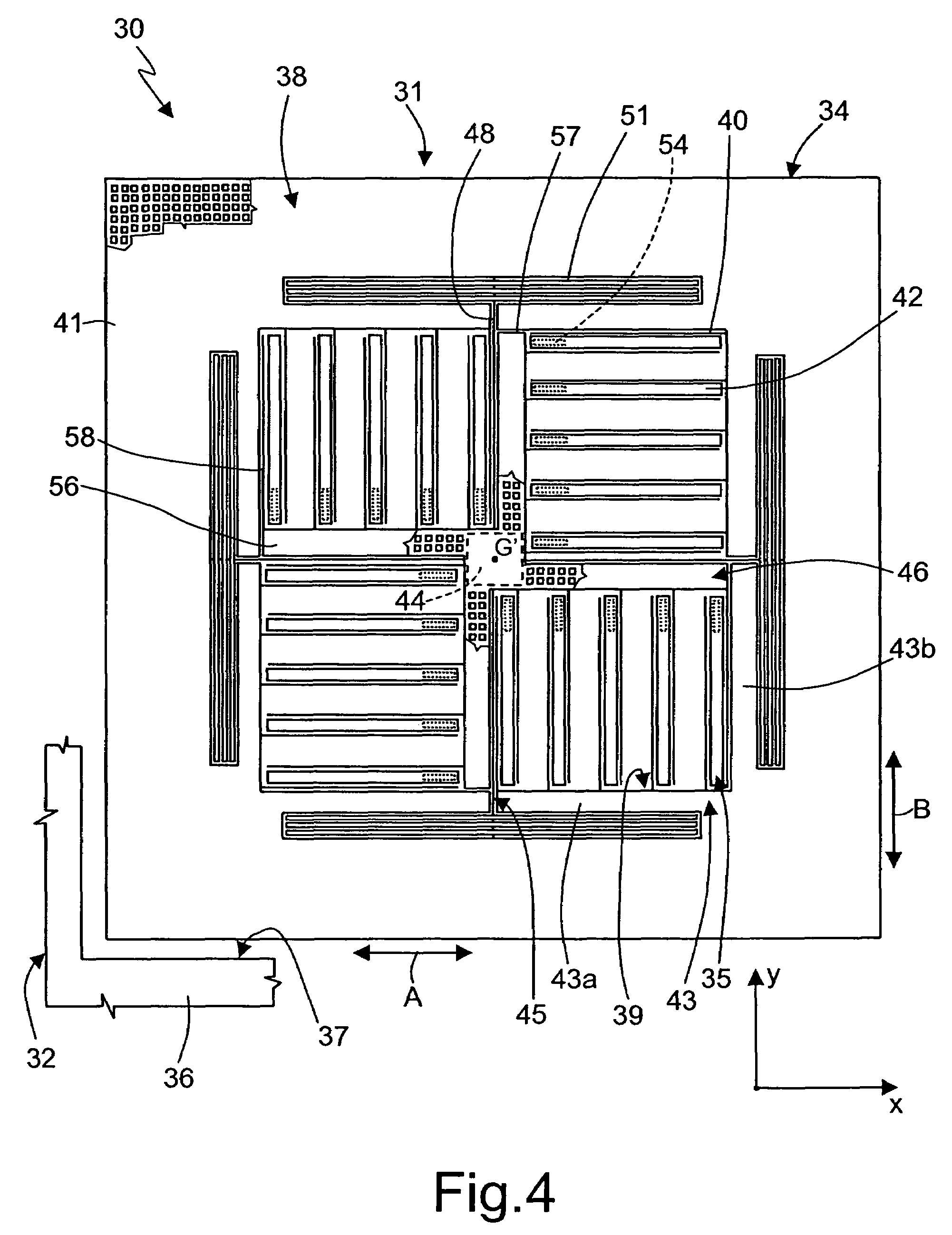
[0037]FIG. 4 shows a biaxial accelerometer 30 of linear type, having a thermal-drifts compensation structure similar to the structure described previously for the uniaxial accelerometer 1.

[0038]The biaxial accelerometer 30, integrated in a chip 32 of semiconductor material, comprises a detection structure 31, formed by a rotor 34 and a stator 35. The biaxial accelerometer 30 has a centroidal axis G′.

[0039]In detail, the rotor 34 comprises a suspended mass 38, which has a peripheral region 41 substantially square frame-shaped, may be surrounded by a fixed structure 36 and may be separated therefrom by a peripheral trench 37.

[0040]The suspended mass 38 may be supported and biased by a suspension structure, comprising a rotor-anchoring element 44 and elastic elements 45.

[0041]The rotor-anchoring element 44 has a substantially square shape, may be centered on the centroidal axis G′, and may be anchored to the substrate (not illustrated) of the chip 32.

[0042]The elastic elements 45 enabl...

second embodiment

[0055]With the second embodiment it is possible to arrange stator anchorages, common to a plurality of fixed electrodes 63, in the proximity of the centroidal axis G′ of the structure and hence in the proximity of the rotor-anchoring portion 44. Thereby, minimization of the relative displacements between the stator and rotor anchorages and thus minimization of the thermal drifts due to the deformation of the chip may be obtained. The smaller the drifts to be compensated, the greater the effectiveness of the self-compensation ensured by the compensation structure according to the present invention.

[0056]With the accelerometers described, it may be possible to integrate the compensation structure within the micro-electromechanical structure, without requiring additional electronic components and without the need for complicated setting and calibration procedures. In practice, a self-compensation in temperature may be obtained that is intrinsic to the micro-electromechanical structure....


PUM


Abstract

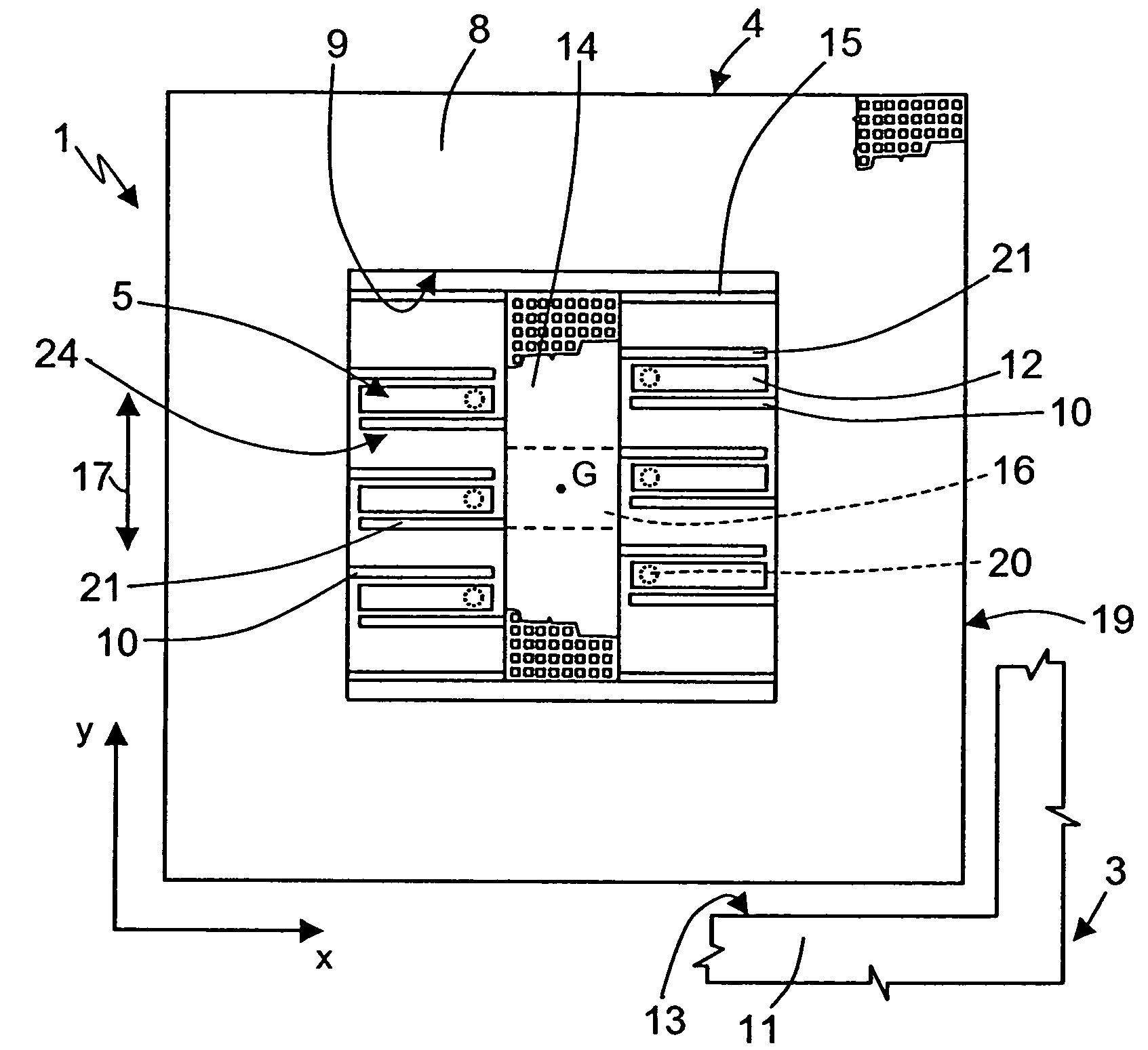
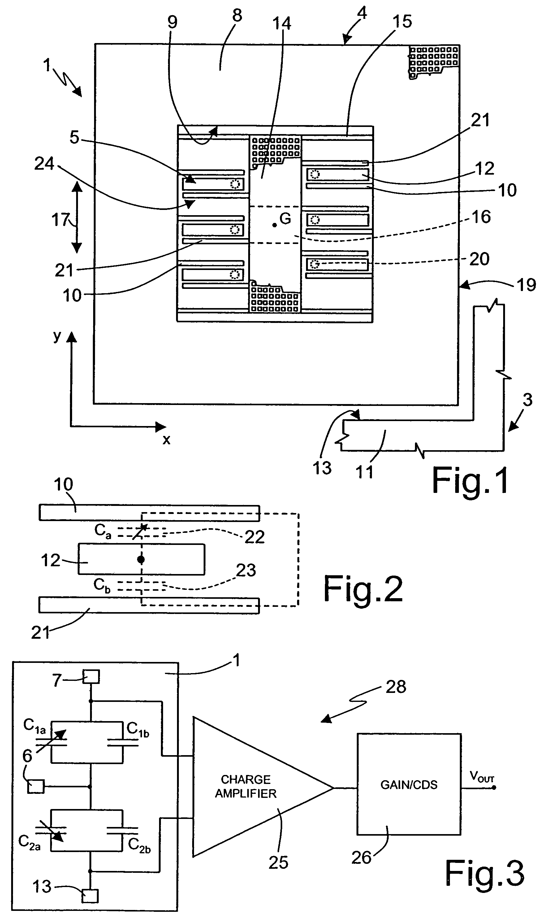
In a micro-electromechanical structure of semiconductor material, a detection structure is formed by a stator and by a rotor, which are mobile with respect to one another in presence of an external stress and are subject to thermal stress; a compensation structure of a micro-electromechanical type, subject to thermal stress and invariant with respect to the external stress, is connected to the detection structure thereby the micro-electromechanical structure supplies an output signal correlated to the external stress and compensated in temperature.

Description

BACKGROUND OF THE INVENTION[0001]1. Field of the Invention[0002]The present invention relates to a micro-electromechanical structure with self-compensation of the thermal drifts caused by thermomechanical stress.[0003]2. Description of the Related Art[0004]The following description will make reference, to an inertial sensor, in particular to a linear accelerometer, without losing generality. As is known, micromachining techniques enable micro-electromechanical structures (MEMS) to be obtained within layers generally of semiconductor material, which have been deposited (for example, a polycrystalline silicon layer) or grown (for example, an epitaxial layer) on top of sacrificial layers, which are removed via etching.[0005]In particular, inertial sensors obtained using micromachining techniques comprise mobile regions (rotor regions) suspended with respect to a substrate, and fixed regions (stator regions) anchored and fixed to the substrate and in particular to the package of the sen...

Claims


Application Information

Patent Timeline
Patent Type & Authority Patents(United States)
IPC IPC(8): G01P15/125G01P3/00
CPCG01P15/125G01P2015/082
Inventor MERASSI, ANGELOZERBINI, SARAHVIGNA, BENEDETTO
Owner STMICROELECTRONICS SRL
Learn More