
Impulse driving method and apparatus for liquid crystal device

a technology of liquid crystal devices and driving methods, applied in the direction of instruments, static indicating devices, etc., can solve the problems of image dragging, significant limitation of black insertion ratio, and relatively complicated control signals, and achieve the effect of simplifying the control signal scheme and easy control

Inactive Publication Date: 2009-04-14
HANNSTAR DISPLAY CORPORATION
View PDF30 Cites 16 Cited by
  • Summary
  • Abstract
  • Description
  • Claims
  • Application Information

AI Technical Summary

Benefits of technology

The present invention provides an impulse driving method and apparatus for an LCD that simplifies controlling signals and manipulates the black insertion ratio of the LCD with ease. The invention includes an impulse driving apparatus comprising a timing controller, data driver, and gate driver, which work together to output pixel data and control signals. The data driver sequentially outputs pixel data and black data for driving the pixels of the LCD. The gate driver generates scan signals to control the gate lines of the LCD. The invention also includes an impulse driving apparatus with multiple driver integrated circuits that are controlled by the first and second output enable signals. The invention simplifies the controlling signal scheme and allows for easy manipulation of the black insertion ratio with a predetermined period.

Problems solved by technology

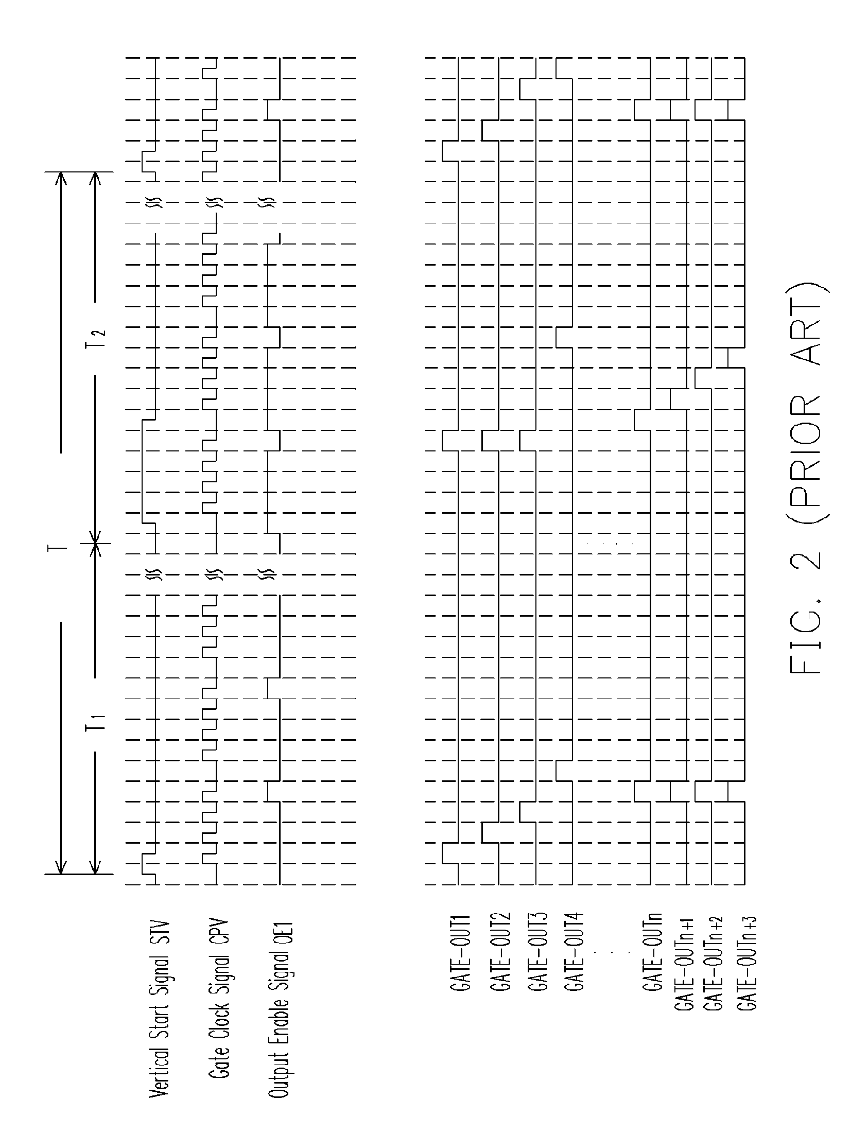
Obviously, the operation method is suitable for static image display, yet when displaying rapid dynamic images, image dragging may occur since storage capacitors are not being promptly charged / discharged.
Therefore, the different driver ICs of this driving method are controlled respectively by the different output enable signals OE1, OE2 and OE3, and thus control signals are relatively complicated.
Consequently, black insertion ratio is significantly limited.

Method used


Image

  • Impulse driving method and apparatus for liquid crystal device
  • Impulse driving method and apparatus for liquid crystal device
  • Impulse driving method and apparatus for liquid crystal device

Examples


Embodiment Construction

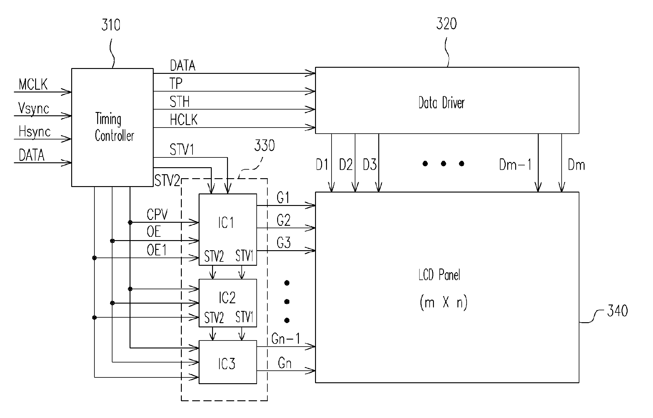
[0028]Referring to FIG. 3, a schematic block diagram of an impulse driving apparatus of an LCD according to one embodiment of the present invention is shown. In FIG. 3, the impulse driving apparatus of the LCD comprises a timing controller 310, a data driver 320 and a gate driver 330 for operating with the LCD panel 340 in the driving diagram. The gate driver 330 according to the embodiment comprises at least two driver integrated circuits, e.g. three of IC1, IC2 and IC3 integrated circuits. However, it is to be noted that number of integrated circuits featuring the gate driver 330 is not limited thereto, which varies according to the requirements.

[0029]The timing controller 310 is for outputting DATA comprising pixel data, black data, and control signals including a load signal TP, a horizontal start signal STH, a horizontal clock signal HCLK, a first start vertical signal STV1, a second start vertical signal STV2, a gate clock signal CPV, a first output enable signal OE and a seco...


PUM


Abstract

An impulse driving method and apparatus thereof for a liquid crystal display (LCD) are provided. The gate driver of the liquid crystal device generates first scan signals for controlling gate lines of the liquid crystal device according to the received first start vertical signal and first output enable signal. The scan signals are generated corresponding to the pixel data signals outputted from the data driver of the LCD. Moreover, the gate driver of the LCD generates second scan signals according to the received second start vertical signal and second output enable signals. The scan signals are generated corresponding to black data signals output from the data driver of the liquid crystal device. Therefore, the control signal scheme is simplified and the black insertion ratio is easily controlled.

Description

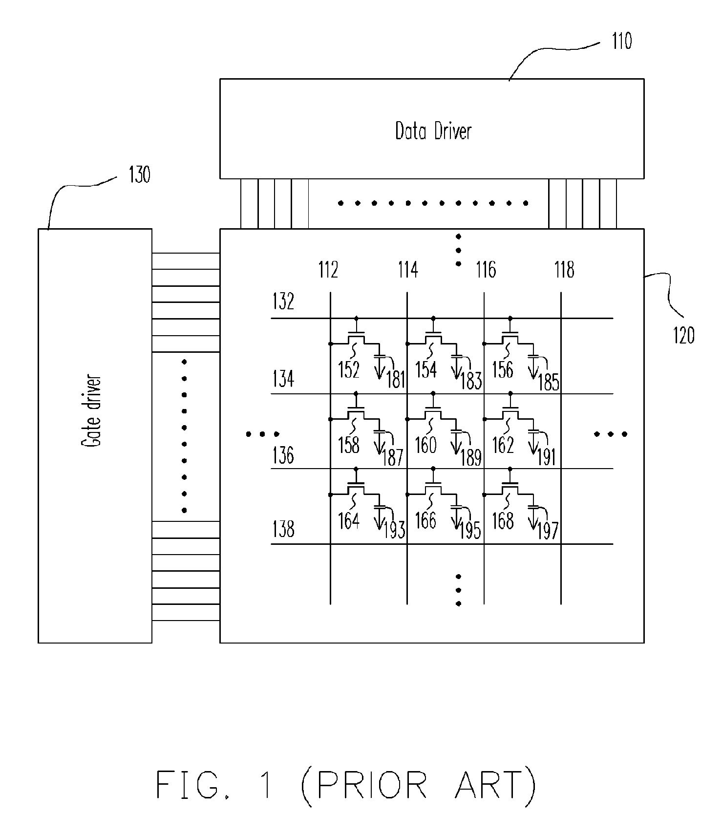
CROSS-REFERENCE TO RELATED APPLICATION[0001]This application claims the priority benefit of Taiwan application 93113597, filed on May 14, 2004, a full disclosure of which is incorporated herein by reference.BACKGROUND OF THE INVENTION[0002]1. Field of the Invention[0003]The present invention relates to a liquid crystal device, and more particularly, to an impulse driving method and apparatus thereof for a liquid crystal device.[0004]2. Description of Related Art[0005]A liquid crystal display (LCD) is broadly used instead of a cathode radiation tube (CRT) in recent time. As semiconductor technology development advances, an LCD is superior in low power consumption, lightness in weight, high resolution, high hue saturation, prolonged lifetime, etc. Therefore, an LCD is broadly used in electronic products such as laptop computer, desktop computer and LCD television. Wherein the quality of a liquid crystal panel dominates the quality of the LCD.[0006]Referring to FIG. 1, a conventional T...

Claims


Application Information

Patent Timeline
Patent Type & Authority Patents(United States)
IPC IPC(8): G09G3/36
CPCG09G3/3648G09G2310/061G09G3/3677
Inventor LEE, SSU-MINGSHIN, SEOBPAI, FENG-TINGCHOU, HSIEN-WEN
Owner HANNSTAR DISPLAY CORPORATION
Learn More