
Staple refill with backward movement preventing member

a technology of backward movement and preventive member, which is applied in the field of staple refills, can solve the problems of increased load applied onto the feeding means for feeding heavy weight and difficulty in feeding the leading end portion of the sheet-like connected staple. achieve the effect of convenient assembly

Active Publication Date: 2009-04-07
MAX CO LTD
View PDF20 Cites 4 Cited by
  • Summary
  • Abstract
  • Description
  • Claims
  • Application Information

AI Technical Summary

Benefits of technology

The invention provides a staple refill that can be attached to a stapler or cartridge. The refill includes a storage portion for storing a sheet-like connected staple, a discharge port for discharging the staple, and a delivery passage for delivering the leading end of the staple to the discharge port. A backward movement preventing member is provided in the delivery passage to prevent the staple from moving towards the storage portion. The refill may also include a projection strip to smoothly rotate the staple. The technical effects of the invention include improved storage and delivery of staples, prevention of staple movement, and smoother staple rotation.

Problems solved by technology

Therefore, there is a problem that a weight of the sheet-like connected staple is applied to the feeding means as a load.
In drawing forth the sheet-like connected staple, because the whole sheet-like connected staple is moved forward, the sheet-like connected staple abuts on an inner surface of the storage portion, and the larger-than designed load is applied to the feeding means due to friction action, which results in the problem that it is difficult for the feeding means to feed the leading end portion of the sheet-like connected staple.
However, when contact pressure is excessively strong in the slide, the load applied onto the feeding means for feeding the sheet-like connected staple is increased.
On the other hand, when the contact pressure is excessively weak in the slide, drawing-back resistance of the sheet-like connected staple is decreased.
Therefore, there is the problem that the backward movement preventing member is difficult to adjust.
Therefore, the backward movement preventing member does not behave well in some cases because the backward movement preventing member slips.
Further, the backward movement preventing members slide on both sides of the sheet-like connected staple across the adhesive tape, and there is a possibility that the sheet-like connected staple is bent when one of the backward movement preventing members does not behave well.
There is also the problem that both the backward movement preventing members are difficult to adjust so as to behave well in the same manner.
Therefore, there is the problem that the backward movement preventing member cannot easily be installed in the refill.
In the conventional staple refill, because the backward movement preventing member made of a metal material is installed, it is necessary to separate the backward movement preventing member into each material in disposal, which results in the problem that the disposal of the backward movement preventing member becomes troublesome.
When the sheet-like connected staple is drawn toward the discharge port side, because the whole outer surface of the sheet-like connected staple is rotated while sliding on the bottom surface of the storage portion, the frictional resistance is increased, which results in the problem that the load applied onto the feeding means for feeding the sheet-like connected staple becomes large.
In the conventional staple refill, the sheet-like connected staple wound in a roll shape is stored in the storage portion of the refill, and the sheet-like connected staple is oscillated in the storage portion during transportation, which results in the possibility that the sheet-like connected staple wound in a roll shape is released.
Further, in the opaque refill, the inside of the refill cannot be seen, which results in the problem that a state of the sheet-like connected staple and a remaining amount of sheet-like connected staple cannot be confirmed.

Method used


Image

  • Staple refill with backward movement preventing member
  • Staple refill with backward movement preventing member
  • Staple refill with backward movement preventing member

Examples


Embodiment Construction

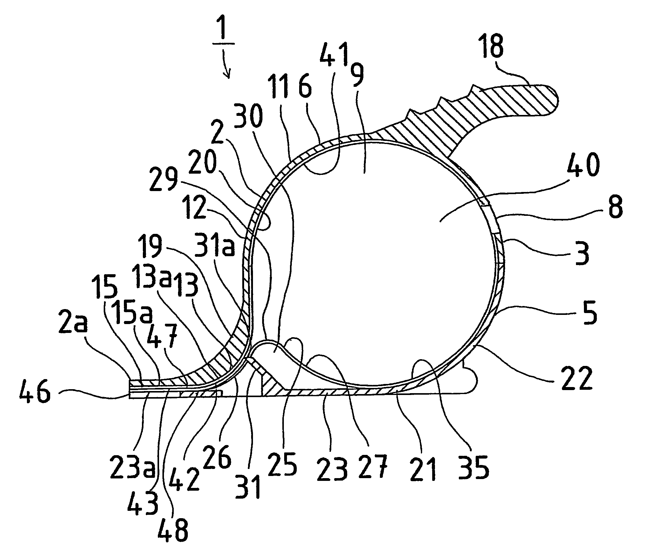
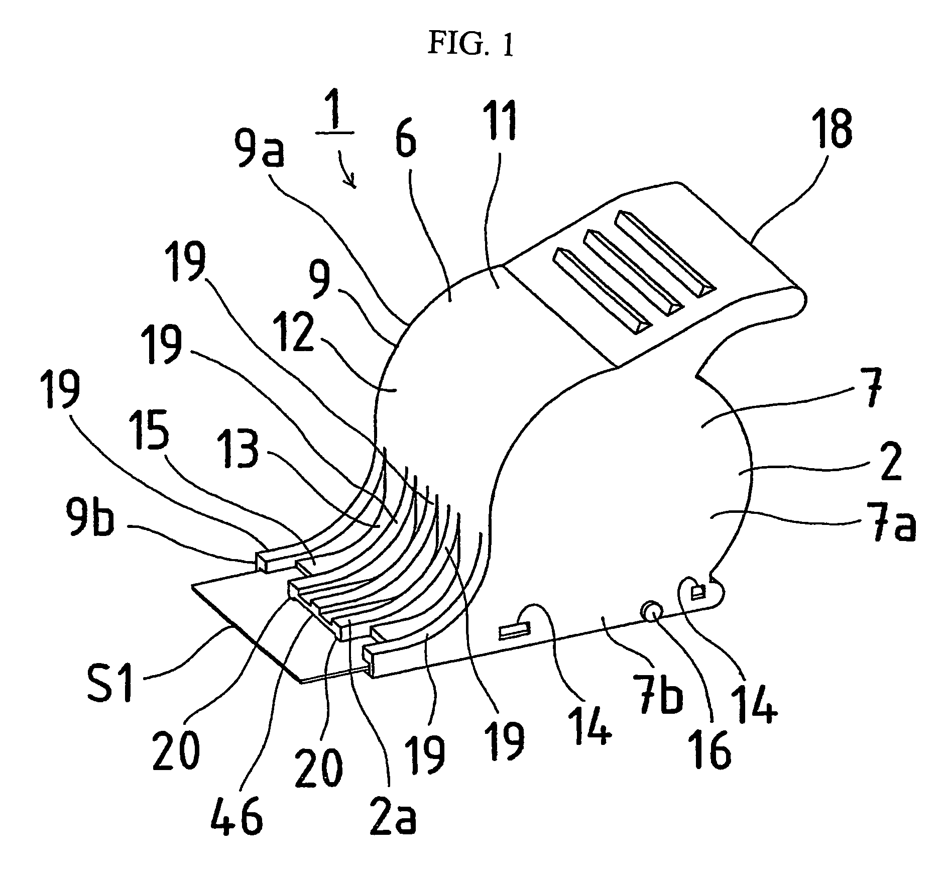
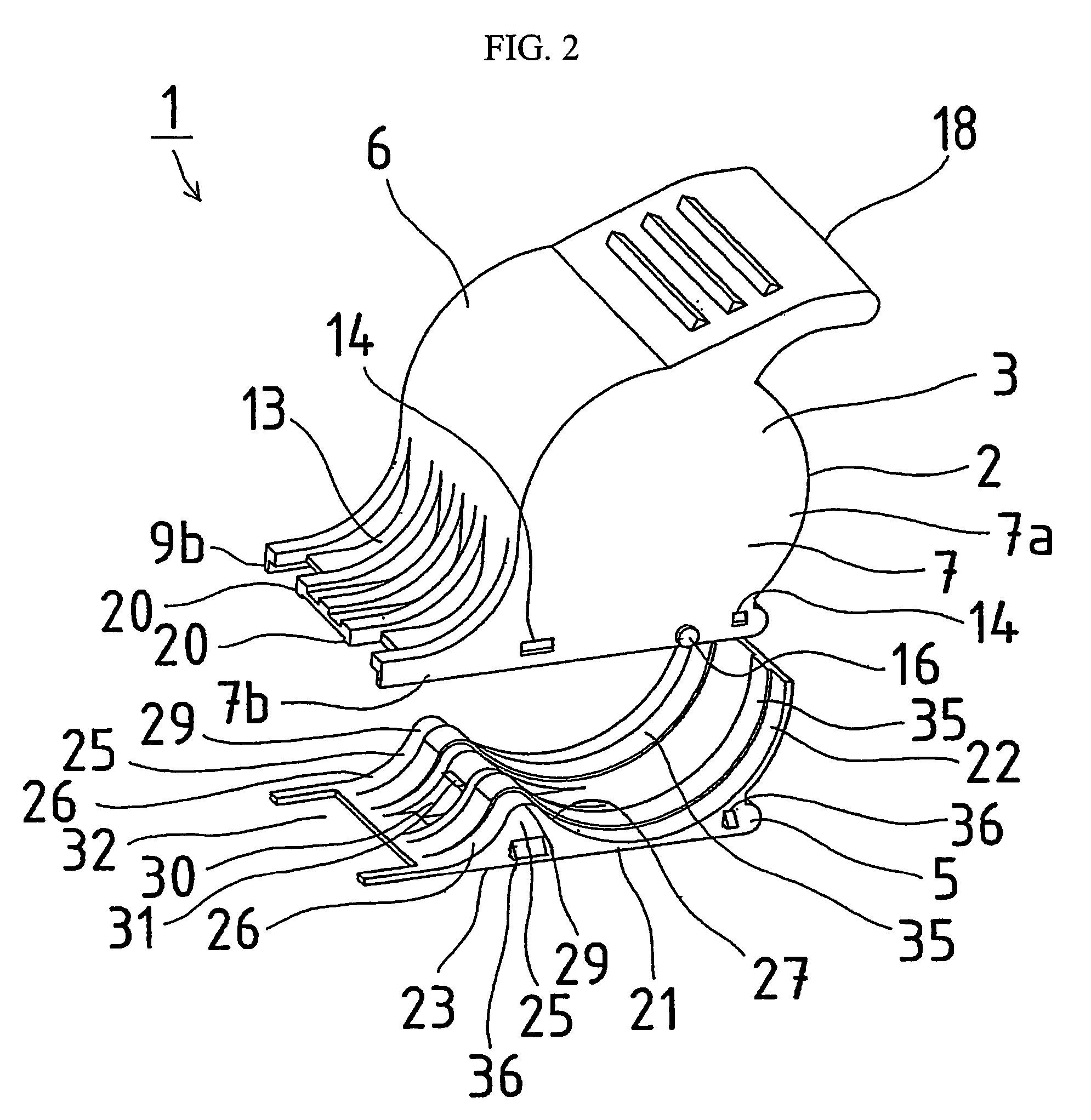
[0031]Embodiments of a staple refill according to the invention will be described below with reference to FIGS. 1 to 10. FIG. 1 is an overall perspective view showing an embodiment of a staple refill according to the invention. FIG. 2 is an exploded perspective view of FIG. 1. FIG. 3 is a sectional perspective view of FIG. 1. FIG. 4 is a sectional side view of FIG. 1. FIG. 5 is a six-side view of the staple refill of FIG. 1, FIG. 5A is a top view when the staple refill is viewed from above, FIG. 5B is a front view when the staple refill is viewed from a front side, FIG. 5C is a side view when the staple refill is viewed from a side face, FIG. 5D is a bottom view when the staple refill is viewed from below, and FIG. 5E is a rear view when the staple refill is viewed from a rear side. FIG. 6 is a sectional view showing a main part of FIG. 1. FIG. 7 is a perspective view showing a state in which the staple refill is attached to a cartridge of a stapler main body. FIG. 8 is an explanato...


PUM


Abstract

A staple refill which can be stored in a refill storing section in such a manner that the leading one of the sheet-like joined staples wound in roll form is on the upper side and which is adapted to lessen the load on a feeding mechanism for feeding the leading one of the sheet of joined staples in a stapler main body. The staple refill is removably attached to a cartridge installed in a stapler main body. A refill includes a storing section for storing a sheet of joined staples wound in roll form, a discharge port for discharging the sheet of joined staples, and a lead-out passage for leading out the leading part of the sheet of joined staples into the discharge port. The lead-out passage is upwardly bent from the discharge port toward the interior of the storing section, so that the leading part positioned on the upper side of the sheet of joined staples is lead out to the discharge port. The lead-out passage is provided with a retrograde motion preventive member which prevents movement of the sheet of joined staples to the storing section.

Description

[0001]This disclosure is based upon Japanese Application No. 2003-308099 filed Aug. 29, 2003 and International Application No. PCT / JP2004 / 012774, filed Aug. 27, 2004, the contents of which are incorporated herein by reference.FIELD OF THE INVENTION[0002]The present invention relates to a staple refill in which a sheet-like connected staple wound in a roll shape is stored.BACKGROUND OF THE INVENTION[0003]For example, as disclosed in Japanese patent Application Laid-Open No. H9-136271 (Patent Reference 1), the conventional staple refill in which the sheet-like connected staple wound in a roll shape is stored has a refill which is detachably attached to a stapler main body or a cartridge provided in the stapler main body. The refill includes a storage portion in which the sheet-like connected staple is stored, a discharge port which discharges the sheet-like connected staple stored in the storage portion, and a delivery passage which delivers a leading end portion of the sheet-like con...

Claims


Application Information

Patent Timeline
Patent Type & Authority Patents(United States)
IPC IPC(8): B27F7/38B25C5/16B65D85/24
CPCB27F7/38Y10T428/2395B27F7/36
Inventor KISHI, KAZUHIKOSHIMIZU, TOSHIOHIGUCHI, KAZUO
Owner MAX CO LTD
Learn More