Resuscitators

a technology of resuscitation device and resuscitation tube, which is applied in the field of resuscitation device, can solve the problems of insufficient flexibility of resuscitation device gas administration, inability to provide inappropriate breathing rate with possible danger to patients, and difficulty in delivering resuscitation devi

Active Publication Date: 2009-04-07
SMITHS MEDICAL INT
View PDF11 Cites 4 Cited by
  • Summary
  • Abstract
  • Description
  • Claims
  • Application Information

AI Technical Summary

Benefits of technology

[0005]The resuscitator may be arranged to deliver repeated ventilation cycles while the manual member is actuated and the resuscitator preferably includes a locking device for holding the manual member in an actuated position. The manual member may include a button that is depressed to actuate a gas delivery cycle, the locking device including a rotatable member operable to retain the button in an actuated position. The rotatable member may extend around the button and be arranged to depress the button when rotated. The rotatable member and the button preferably have cooperating cam formations. The resuscitator preferably includes a first valve controlled by operation of the manual member and a bi-stable valve connected with the first valve to be operated between a fully open or a fully closed position by an output from the first valve, the bi-stable valve controlling supply of gas to the outlet of the resuscitator. The resuscitator preferably includes a timing valve operable to supply cycles of ventilation gas to a patient valve assembly, the output of the timing valve being connected to a manual valve assembly operable by the manual member to prevent or enable flow of ventilation gas to the patient valve assembly, and the output of the manual valve assembly being connected to a control inlet of the timing valve. The resuscitator may include a manually-displaceable control member that is displaceable to alter timing frequency and flow rate simultaneously. The resuscitator may include a gas entrainment device, the manually-displaceable control member being operable also simultaneously to control supply of entrainment gas to the entrainment device. The manually-displaceable control member preferably includes a rotatable member.

Problems solved by technology

Existing resuscitators suffer from various problems.
For example, where the resuscitator can be operated fully manually, there is a risk that an inexperienced operator could provide inappropriate rates of breathing with possible danger to the patient.
Other resuscitators do not allow sufficient flexibility in the administration of gas.

Method used


Image

  • Resuscitators
  • Resuscitators
  • Resuscitators

Examples


Embodiment Construction

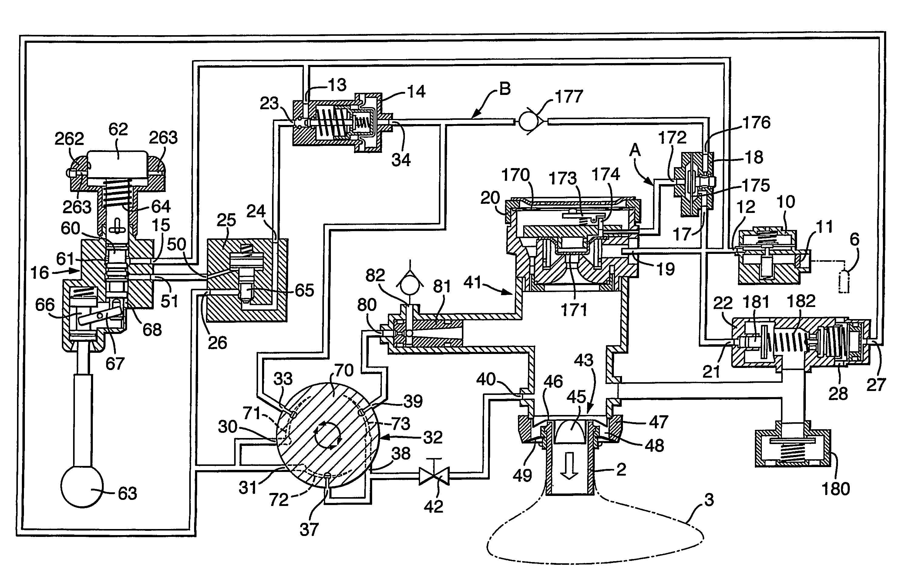
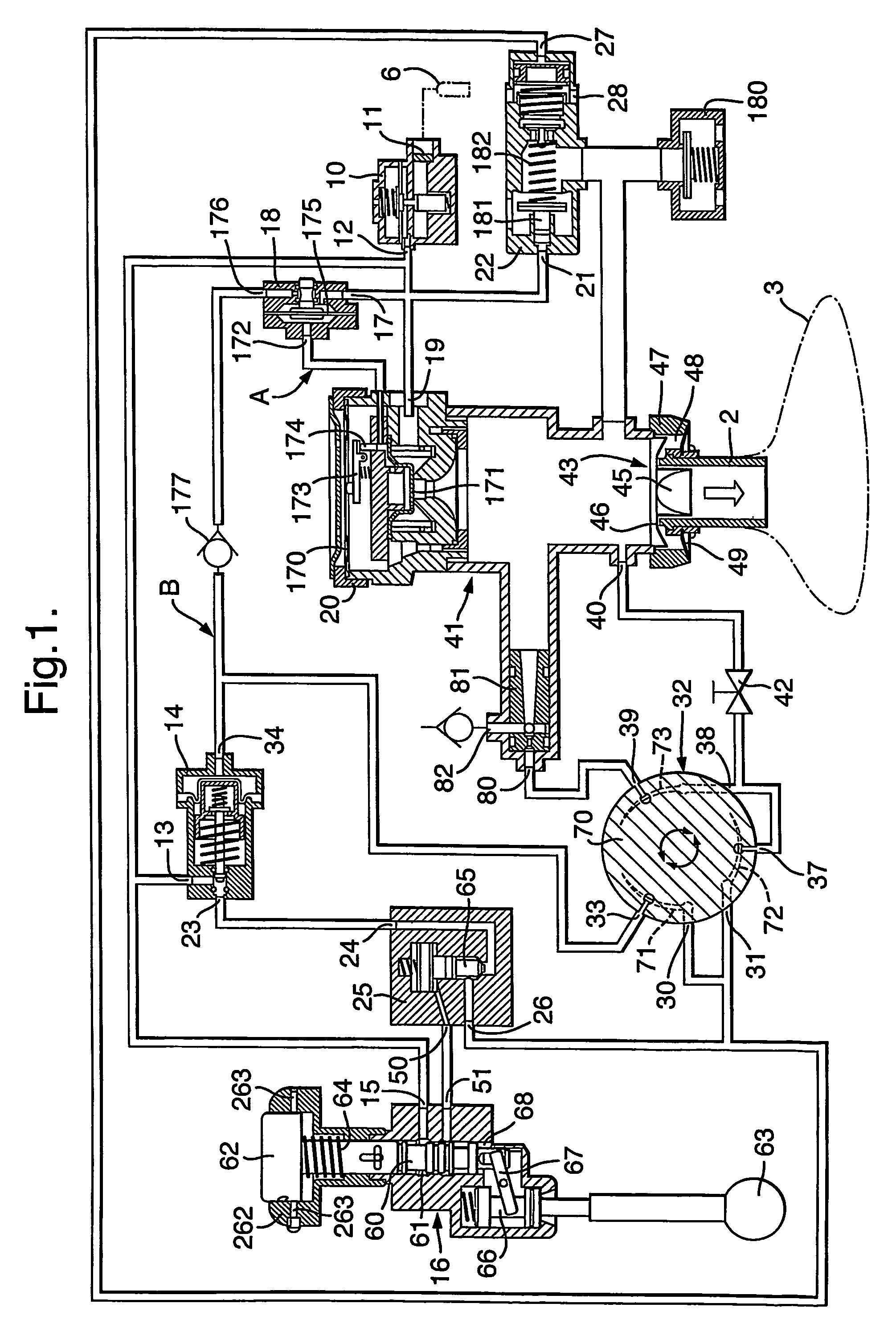
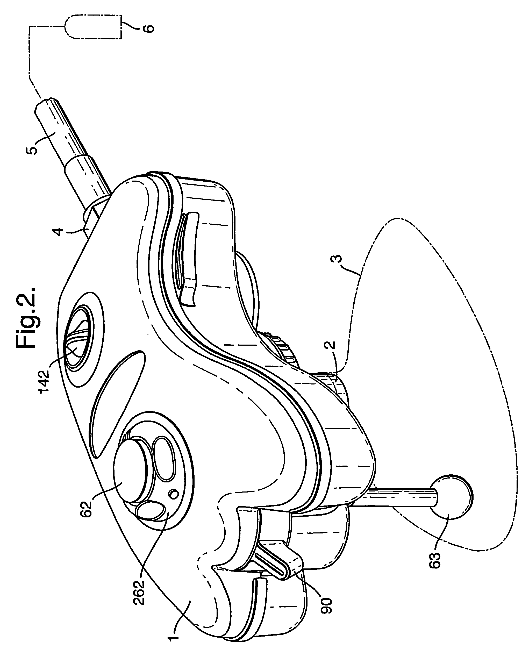
[0013]With reference first to FIGS. 1 and 2 there is shown the various components of the resuscitator and their interconnections. All the components are contained within a common housing 1, which is sufficiently compact and light to be hand held and connected at its patient outlet 2 directly to a face mask 3. The inlet 4 of the resuscitator is connected via flexible tubing 5 to a source of oxygen, such as a cylinder 6 or, for example, a hospital pipeline, delivering pressure between 40 and 150 psi. This arrangement enables single-handed operation, the same hand holding the face mask 3 and controlling the resuscitator. Alternatively, however, the resuscitator could be located adjacent the oxygen cylinder and its patient outlet connected to a face mask or breathing tube via flexible tubing.

[0014]The inlet 4 is provided by a pressure regulator 10 including a filter 11 and an outlet 12, which connects oxygen to various of the other components in the resuscitator. The oxygen splits into ...


PUM


Abstract

A gas-powered resuscitator is operable either in a manual mode or an automatic mode. The resuscitator includes an oscillatory timing valve (14) having an outlet (23) connected to a bi-stable valve (25), the operation of which is piloted by a manual valve (16). The outlet (26) of the bi-stable valve (25) connects to the outlet (2) of the resuscitator via a rotatable control (32) and a patient valve (41). The outlet (26) of the bi-stable valve (25) also connects to the control inlet (34) of the timing valve (14). The manual valve (16) has a button (62) that can be pushed down manually in the manual mode or can be held down in the automatic mode by rotating a locking ring (262). The maximum duration of cycles is limited by operation of the timing valve (14), whether the resuscitator is operated manually or automatically.

Description

FIELD OF THE INVENTION[0001]This invention relates to resuscitators of the kind operable in a first, automatic mode whereby gas is delivered to a patient in a regulated cyclical fashion repeatedly until the mode is terminated and in a second mode whereby a cycle of gas is delivered in response to actuation of a manual member.BACKGROUND OF THE INVENTION[0002]Resuscitators are used to supply breathing gas to a patient who may not be breathing spontaneously. Portable resuscitators may take the form of a resilient bag that is squeezed manually to supply a volume of air to the patient, the bag refilling with air when it is released so that a new volume of air can be supplied. Alternatively, the resuscitator may be a mechanical device including a tiring valve and various other controls and is connected to an oxygen cylinder, which both provides the breathing gas, or a part of this, and which may also provide the power to drive the components of the resuscitator. Examples of such resuscita...

Claims


Application Information

Patent Timeline
IPC IPC(8): A61M11/00A61M16/00A61M16/12A61M16/20
CPCA61M16/00A61M16/20A61M16/127A61M16/107A61M16/208A61M16/201A61M16/206A61M16/209Y10T137/87917
Inventor BEN, JONATHAN KEVINBENNETT, PAUL JAMES LESLIE
Owner SMITHS MEDICAL INT
Why Eureka
Try Eureka