
High-frequency processing of seismic vibrator data

a vibrator and high-frequency technology, applied in the field of seismic data processing, can solve the problems of limited correlation data, non-linear response of the vibrator, and limited data useful bandwidth,

Active Publication Date: 2009-03-24
SCHLUMBERGER TECH CORP
View PDF20 Cites 6 Cited by
  • Summary
  • Abstract
  • Description
  • Claims
  • Application Information

AI Technical Summary

Benefits of technology

This approach improves data quality by reducing noise and effectively using harmonic energy, resulting in higher-frequency geological subsurface images with increased resolution and accuracy.

Problems solved by technology

One commonly seen problem with seismic vibrators is that the response of the vibrator is non-linear such that the vibrator, in addition to the acoustic signal at the intended frequency, sends out energy at higher harmonics, or multiples of this frequency.
However, the correlated section of data will contain improperly placed energy all over, mostly at higher frequencies, eventually limiting the useful bandwidth of the data.
In addition to this, the correlated data will be limited to the same frequency band as the reference signal.
The production of harmonic energy by seismic vibrators is typically difficult to predict and difficult to measure.
While this type of method can offer significant advantages compared to the use of the reference sweep, this type of method typically does a less than perfect job of estimating the source signature actually imparted into the earth by the vibratory seismic source because a sensor mounted on the vibrator can only sense the outgoing seismic wavefield indirectly.
In practice, however, it is often very difficult to clearly distinguish between “noise”, which one would like to remove from the data, and “signal” which must to be substantially retained to allow the subsurface to be adequately characterized.

Method used


Image

  • High-frequency processing of seismic vibrator data
  • High-frequency processing of seismic vibrator data
  • High-frequency processing of seismic vibrator data

Examples


Embodiment Construction

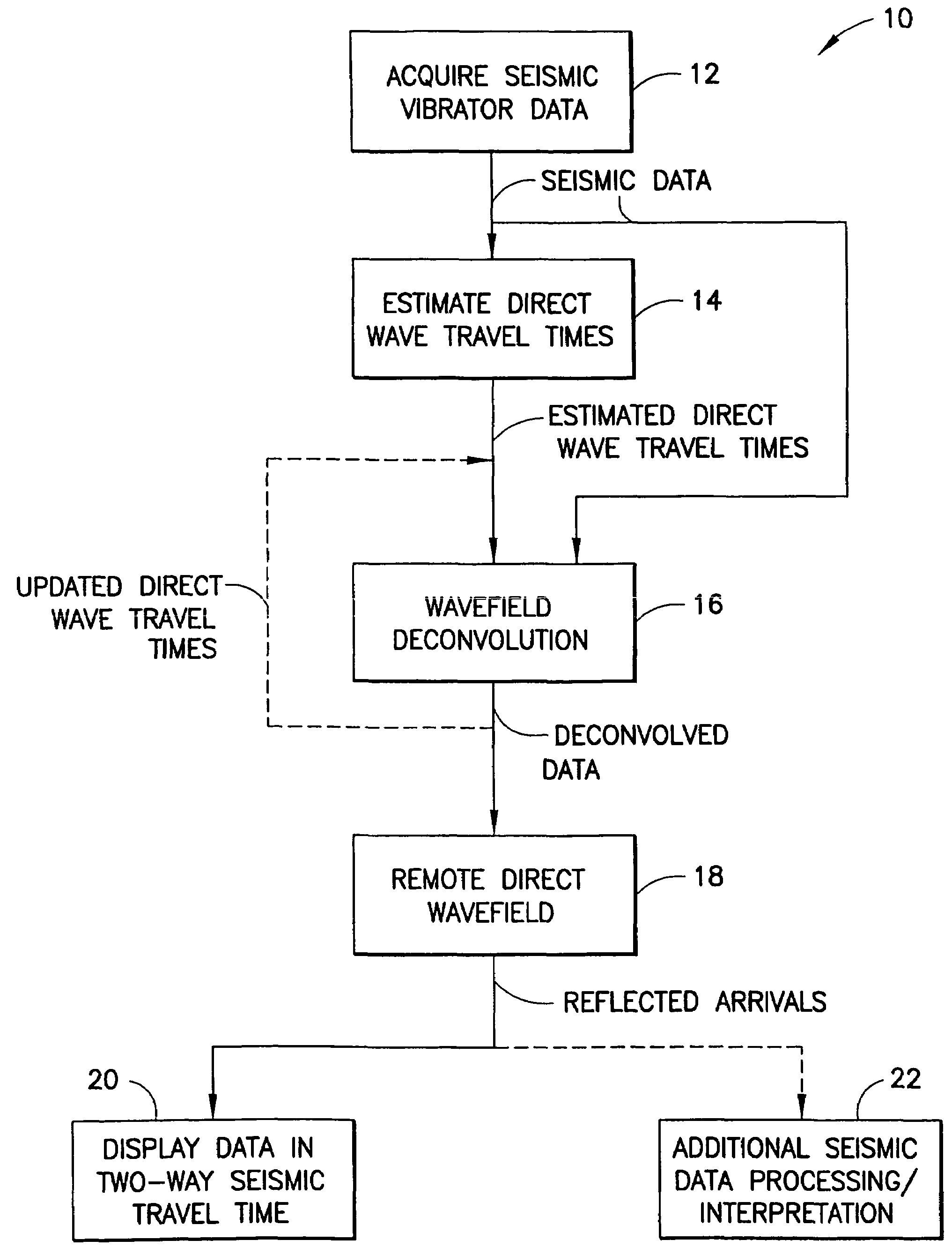
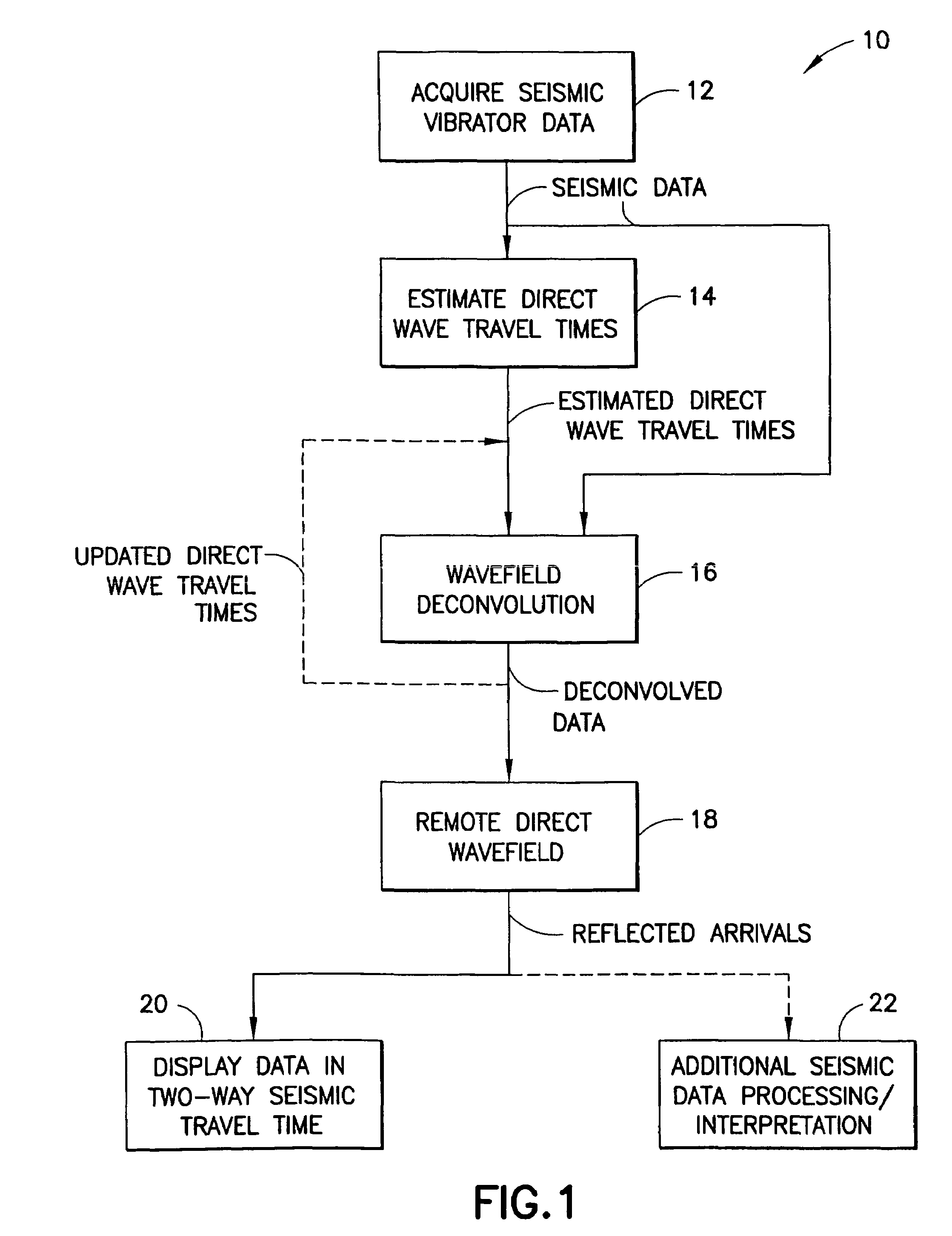
[0026]FIG. 1 is a flowchart that depicts various processes associated with certain embodiments of the present invention. The first process associated with Inventive Procedure 10 is the acquisition of seismic data, including both seismic obtained using a seismic vibrator and surface seismic data, the seismic data having significant harmonic energy using a seismic vibratory source at Acquire Seismic Vibrator Data 12. The direct wave arrival travel times arrivals between the seismic vibrator and an array of seismic receiver locations are then estimated at Estimate Direct Wave Travel Times 14. As discussed below, this process will typically involve correlating the seismic data with either the seismic vibrator reference sweep or an estimate of the actual seismic vibrator source signature and then picking the estimated direct wave arrival times, but other methods can be used to estimate the direct wave arrival travel times between the seismic vibrator and the array of seismic receiver loc...


PUM


Abstract

A method of processing seismic data obtained using a seismic vibrator that includes estimating travel times of direct wave arrivals between the seismic vibrator and an array of seismic receiver locations and wavefield deconvolving the seismic data using the direct wave arrival travel times. Also a related method of producing a high-frequency geological subsurface image that includes acquiring seismic data having significant harmonic energy using a seismic vibrator, estimating direct wave arrival travel times between the seismic vibrator and an array of seismic receiver locations, wavefield deconvolving the seismic data using the estimated direct wave arrival travel times, and using the wavefield deconvolved seismic data to produce a high-frequency geological subsurface image. A further related computer useable medium having computer readable program code means embodied therein practicing the inventive method.

Description

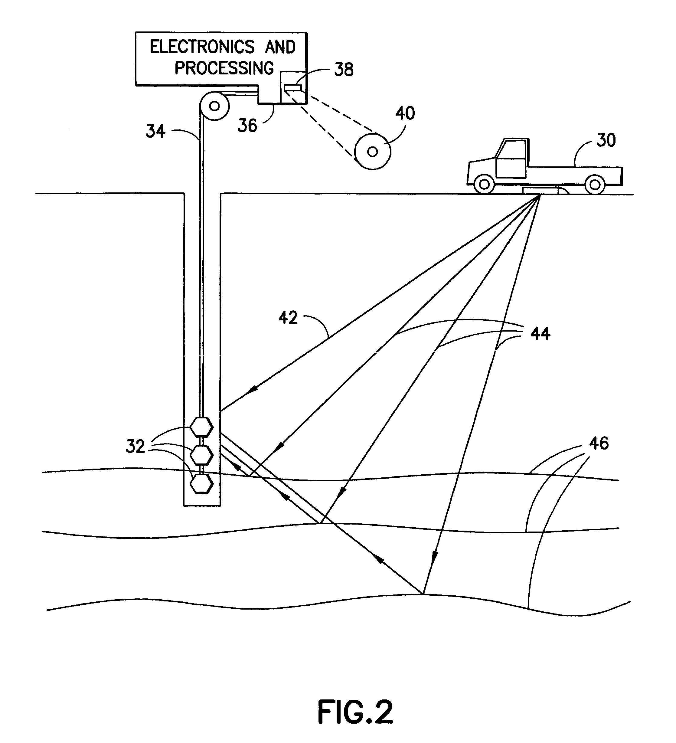
CROSS REFERENCE TO RELATED APPLICATION[0001]This application claims priority from co-pending U.S. Provisional Patent Application No. 60 / 520,175, filed Nov. 14, 2003.FIELD OF THE INVENTION[0002]This invention relates to the processing of seismic data and, more particularly, to the processing of seismic data obtained using a vibratory seismic source where the processing method is able to utilize harmonic energy as signal rather than noise.BACKGROUND[0003]Vibratory seismic sources, typically referred to as seismic vibrators, are commonly used in connection with the acquisition of seismic data, such as vertical seismic profiling (VSP) data. A seismic vibrator is a low-impact (low amplitude), typically hydraulic, source programmed to generate a signal within a certain frequency range. The source's signal has a duration of several seconds, typically around 10 seconds, during which time the driving signal of the vibrator continuously changes from a minimum value, e.g. 8 Hertz, to a maximum...

Claims


Application Information

Patent Timeline
Patent Type & Authority Patents(United States)
IPC IPC(8): G01V1/36G01V1/37
CPCG01V1/37
Inventor HALDORSEN, JAKOB B. U.
Owner SCHLUMBERGER TECH CORP
Learn More