Method and apparatus for patient transfer
- Summary
- Abstract
- Description
- Claims
- Application Information
AI Technical Summary
Benefits of technology
Problems solved by technology
Method used
Image
Examples
first embodiment
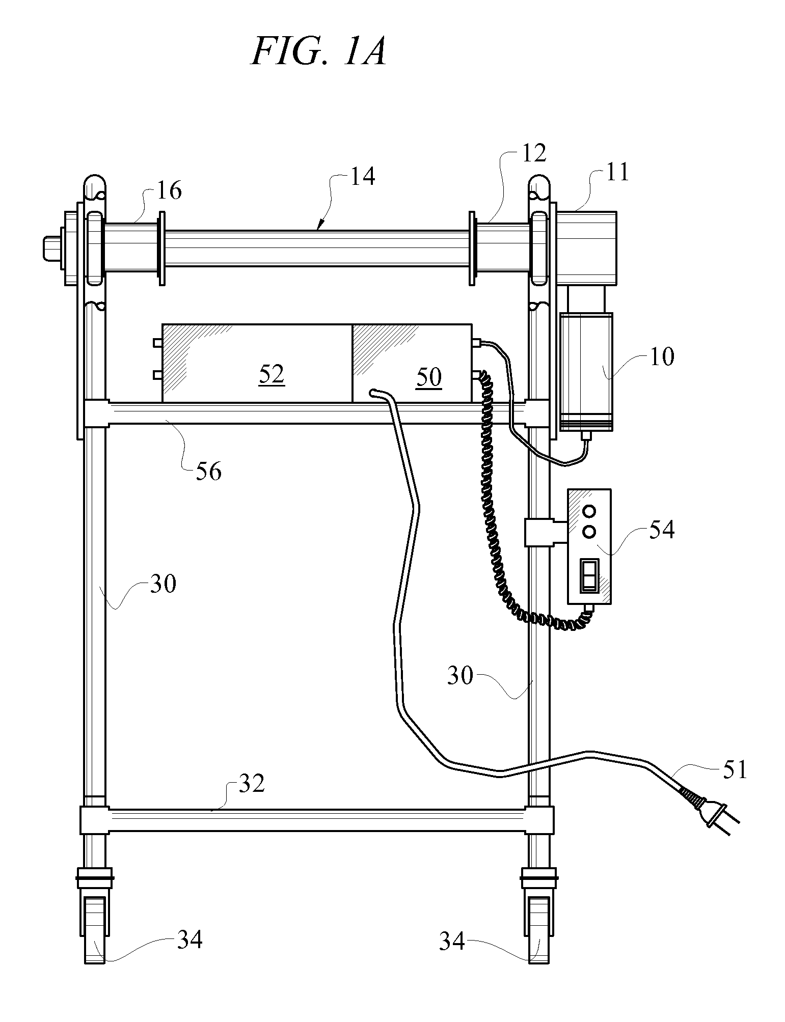
[0030]Referring to FIG. 1A, a front schematic view of a system of the present invention is shown. The patient transfer winch system of this embodiment has one motor 10 that drives a shaft 14 through a gear box 11. The motor is controlled by a controller 50 mounted upon a support rail 56 with a detachable remote control 54. The remote control 54 has switches to control the operation of the motor and indicators to provide status such as battery charge status and system power status. In some embodiments, the switches are in the form of a joystick. The switches include, for example, motor speed and direction controls and an emergency stop. Power to the system is provided by a rechargeable battery 52, for example, a lead acid battery or nickel metal hydride battery. In some embodiments, the batteries are recharged under control of the controller 50 using external power supplied from a standard power source through power cable 51. In some embodiments, the batteries are removable and are e...
second embodiment
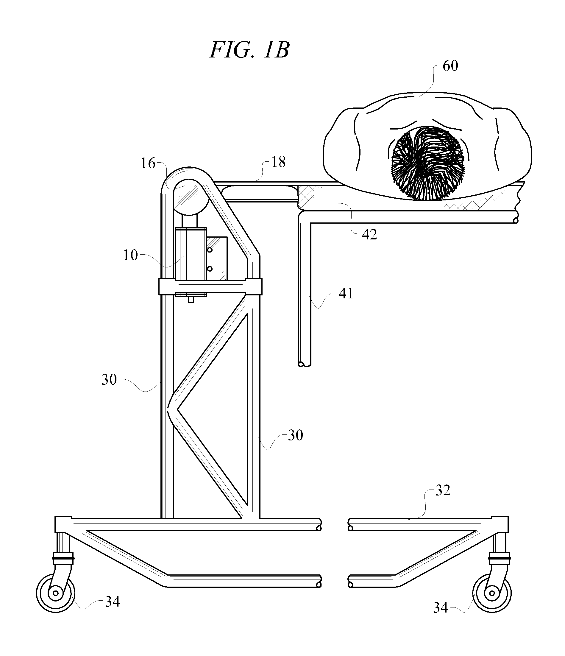
[0032]Referring to FIG. 1B, a side schematic view of a system of the present invention is shown. In this view, more detail of the frame is visible, showing the side of the vertical supports 30 and horizontal supports 32 as well as wheels 34. One of the motors 10 is visible and one of the reels 16 with a patient transfer strap 18 passing under the patient 60, whereas the patient is lying on a surface 42 supported by supports 41.
[0033]Referring to FIG. 2A, a front schematic view of a system of the second embodiment of the present invention is shown. The patient transfer winch system of this embodiment has two hand-cranks 22 / 23 that turn their respective strap reels 12 / 16. The strap reels 12 / 16 are mounted on a shaft 14 and turn independent of the shaft 14 using bearings, etc., as known in the industry. The patient transfer system is supported by vertical supports 30 and horizontal supports 32. In some embodiments, wheels 34 are provided for movement of the winch system.
[0034]Referring...
third embodiment
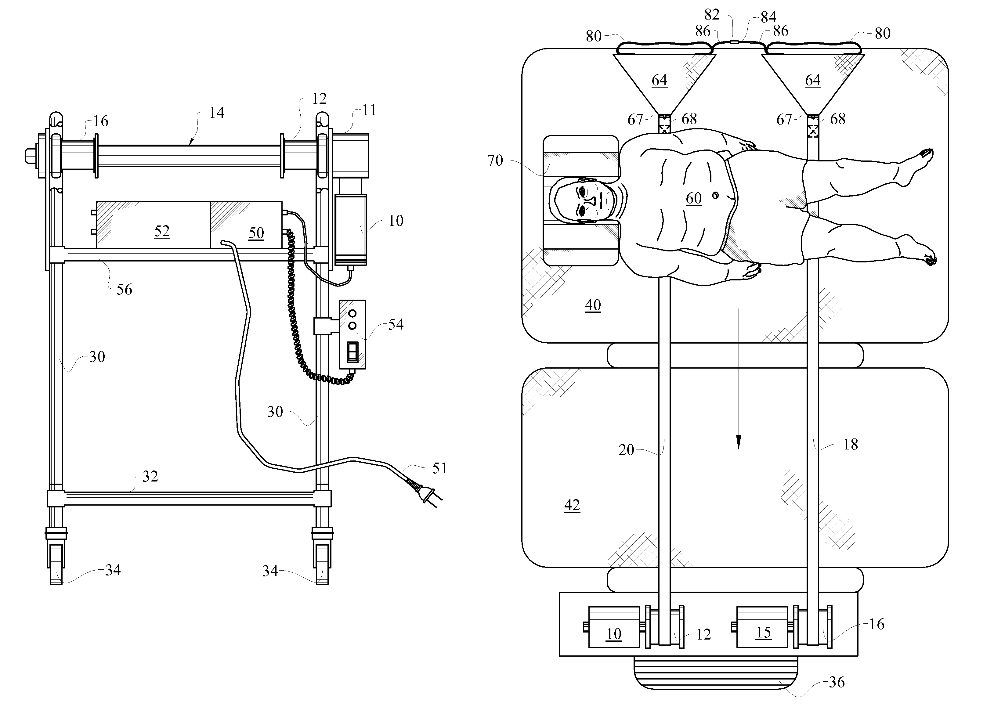
[0035]Referring to FIG. 3, a plan view of a system of the present invention is shown. This embodiment shows two motors 10 / 15, each driving a separate reel 12 / 16. Not shown is the motor control system and remote control as in FIG. 1. In some embodiments, one or two joystick remote controls are provided to allow one-handed operation of both motors.
[0036]A patient transfer strap 20 / 18 is attached to each reel 12 / 16 so that as the motors 10 / 15 turn, the patient transfer straps 20 / 18 wind around the reels 12 / 16. The patient transfer strap is preferably made of a relatively high-strength, flexible material such as polypropylene or polyethylene. Preferably, the straps are made of a smooth, slippery material to aid in passing the straps 20 / 18 underneath the patient. The other ends of the patient transfer straps are passed underneath the patient 60 and are removably attached to a wedge cushion system at attachment points 67.
[0037]To assist with passing the patient transfer straps 20 / 18 under...
PUM
 Abstract
Description
Claims
Application Information
 - R&D
- Intellectual Property
- Life Sciences
- Materials
- Tech Scout
- Unparalleled Data Quality
- Higher Quality Content
- 60% Fewer Hallucinations
Browse by: Latest US Patents, China's latest patents, Technical Efficacy Thesaurus, Application Domain, Technology Topic, Popular Technical Reports.
© 2025 PatSnap. All rights reserved.Legal|Privacy policy|Modern Slavery Act Transparency Statement|Sitemap|About US| Contact US: help@patsnap.com


