Sunshade actuation device
a technology of sunshade and actuation device, which is applied in the direction of roofs, windows, transportation and packaging, etc., can solve the problems of not being able to provide another component in the area between the guide rails, requiring a larger mounting space, and wasting or dead space. , to achieve the effect of small and lightweight, simple structure, and discharge or reduce the force against the foreign member
- Summary
- Abstract
- Description
- Claims
- Application Information
AI Technical Summary
Benefits of technology
Problems solved by technology
Method used
Image
Examples
first embodiment
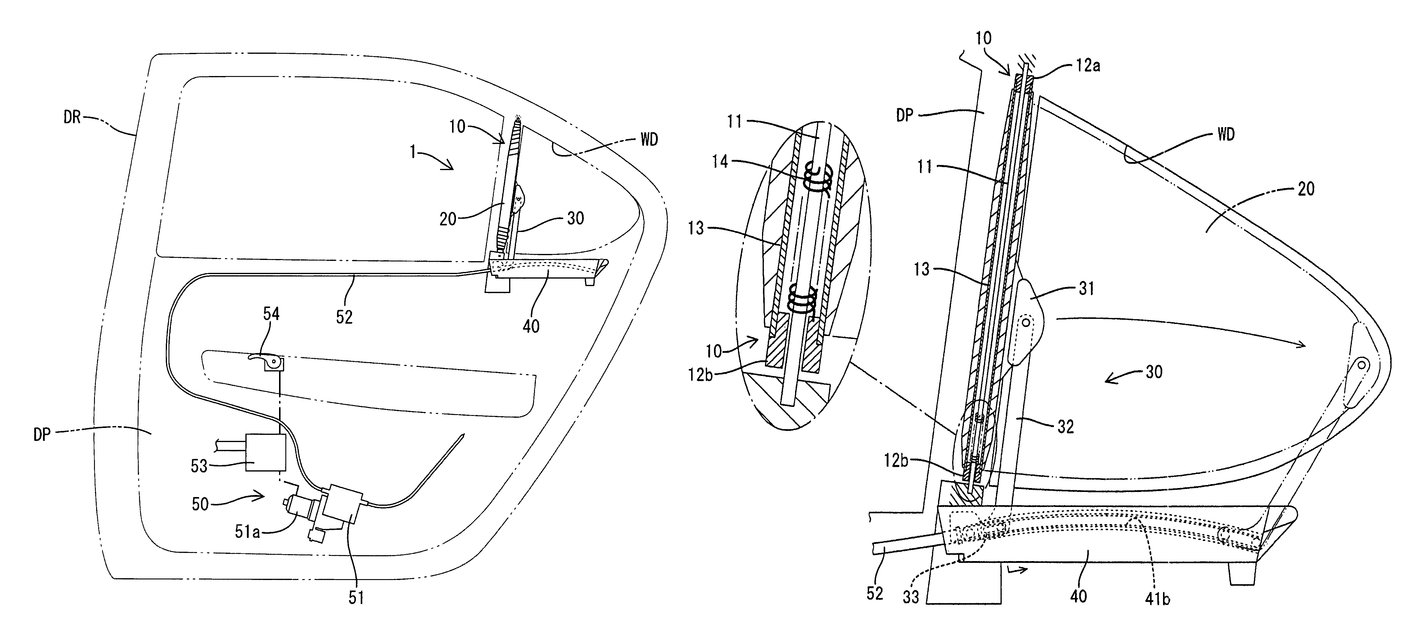
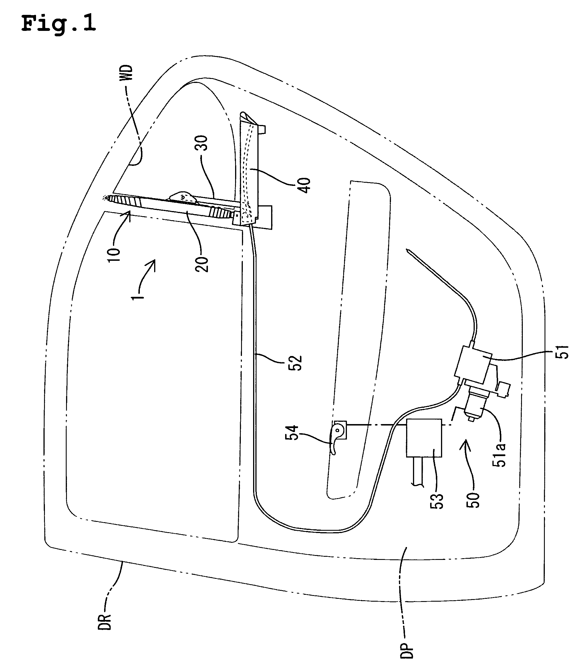
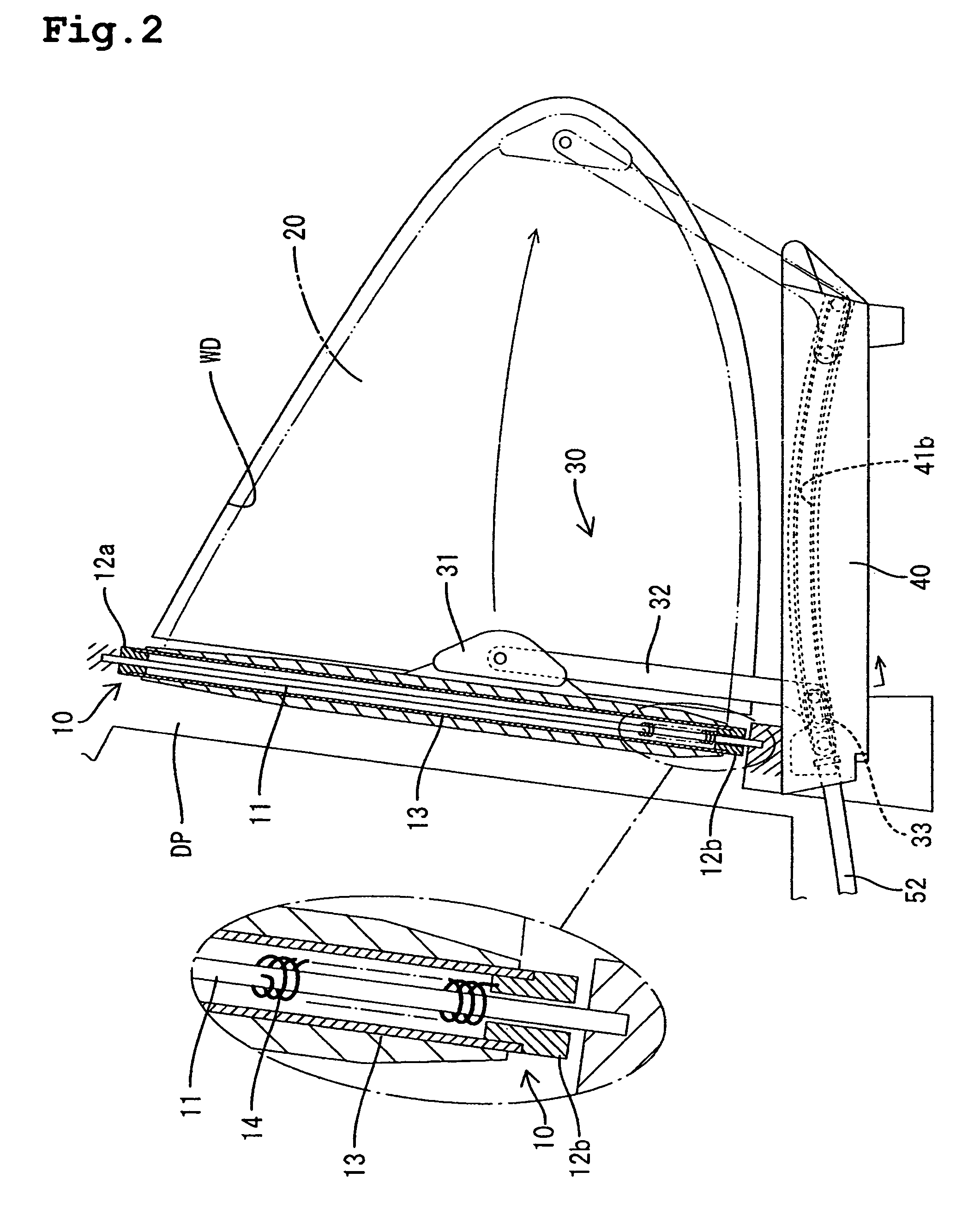
[0031]the present invention will be explained with reference to FIGS. 1 to 6. The left side of the FIG. 1 is referenced as the front in the explanations, the right side is the rear. As shown in FIG. 1, a sunshade actuation device 1 is mounted in a door panel DP, which constitutes a rear door DR of a vehicle. The sunshade actuation device 1 comprises a winder 10, a shade member 20, a swing arm device 30, a guide rail assembly 40, and an actuator device 50.
[0032]The winder 10 (see FIG. 2) (corresponding to an example of a winding device) is arranged proximate to (i.e., in front of) a rear quarter window WD (corresponding to an example of a window) of the rear door DR, and is fixed to the door panel DP. A pair of roller caps 12a and 12b is rotatably mounted to each end of a mounting shaft 11. The mounting shaft 11 is unrotatably fixed to the door panel DP so as to be located proximate to the quarter window WD. In addition, a roller sleeve 13 is integrated with the roller caps 12a and 1...
second embodiment
[0044]the present invention will be explained next with reference to FIG. 7. In a connecting piece 34 (corresponding to an example of the moving part of the present invention) of the swing arm device 30a of this embodiment, an elongated hole 34a extends in an approximately vertical direction. Further, by inserting a rotation pin 32c within this elongated hole 34a, the drawing arm 32 is rotatably connected to the connecting piece 34. Thus, the connecting piece 34 can move relative to the drawing arm 32 in the vertical direction. The difference between the drawing locus of the rear portion of the shade member 20, when the shade member 20 is drawn out from the winder 10 or is wound by the winder 10, and the moving locus of the connecting piece 34, is absorbed by the vertical movement. Therefore, it becomes possible to draw the shade member 20 out, without the generation of wrinkles, through the use of a relatively simple structure.
third embodiment
[0045]FIG. 8 shows the present invention. In this embodiment, the roller caps 12a and 12b and the roller sleeve 13 of a winder 10A are made movable in an axial direction relative to the mounting shaft 11. The roller caps 12a and 12b and the roller sleeve 13 are hung from the mounting shaft 11 by the volute spring 14, intermediately installed between the mounting shaft 11 and the roller cap 12b. Therefore, the roller sleeve 13 can move relative to the mounting shaft 11 in an axial direction (i.e., a vertical direction as viewed in FIG. 8) due to an adequate load. The difference between the drawing locus of the rear portion of the shade member 20, when the shade member 20 is drawn out from the winder 10A or is wound by the winder 10A, and the moving locus of the connecting piece 31, can be absorbed by the vertical movement of the roller sleeve 13. Consequently, it becomes possible to draw the shade member 20 out, without the generation of wrinkles, through the use of a relatively simp...
PUM
 Abstract
Description
Claims
Application Information
 - R&D
- Intellectual Property
- Life Sciences
- Materials
- Tech Scout
- Unparalleled Data Quality
- Higher Quality Content
- 60% Fewer Hallucinations
Browse by: Latest US Patents, China's latest patents, Technical Efficacy Thesaurus, Application Domain, Technology Topic, Popular Technical Reports.
© 2025 PatSnap. All rights reserved.Legal|Privacy policy|Modern Slavery Act Transparency Statement|Sitemap|About US| Contact US: help@patsnap.com


