
Anti-shake system

a technology of anti-shake and power consumption, applied in the field of anti-shake systems, can solve the problems of increasing the power consumption of the anti-shake system, and achieve the effect of reducing the amount of power

Inactive Publication Date: 2009-03-10
RICOH IMAGING COMPANY
View PDF15 Cites 26 Cited by
  • Summary
  • Abstract
  • Description
  • Claims
  • Application Information

AI Technical Summary

Benefits of technology

[0020]According to the present invention, the natural frequency of the movable portion is set within a range of frequencies of camera shake, which results in a reduction in power consumption of the anti-shake system.
[0021]Furthermore, since the spring rate of the resilient member that holds the movable portion can be made small, the amount of driving force for driving the movable portion can be reduced, resulting in less consumption of electrical power, so that if a battery is used for the power source, the battery can be used for a longer period of time before needing replacing.

Problems solved by technology

However, in the anti-shake systems proposed in these patent publications, in order to set the natural frequency within a range of frequencies above the frequency of camera shake, the driving force required for driving the correction optical system or the image pickup device becomes great, to thereby increase the power consumption of the anti-shake system because it is necessary to increase the spring rate of a spring member (or spring members) which holds the correction optical system or the image pickup device.

Method used


Image

  • Anti-shake system
  • Anti-shake system
  • Anti-shake system

Examples


Embodiment Construction

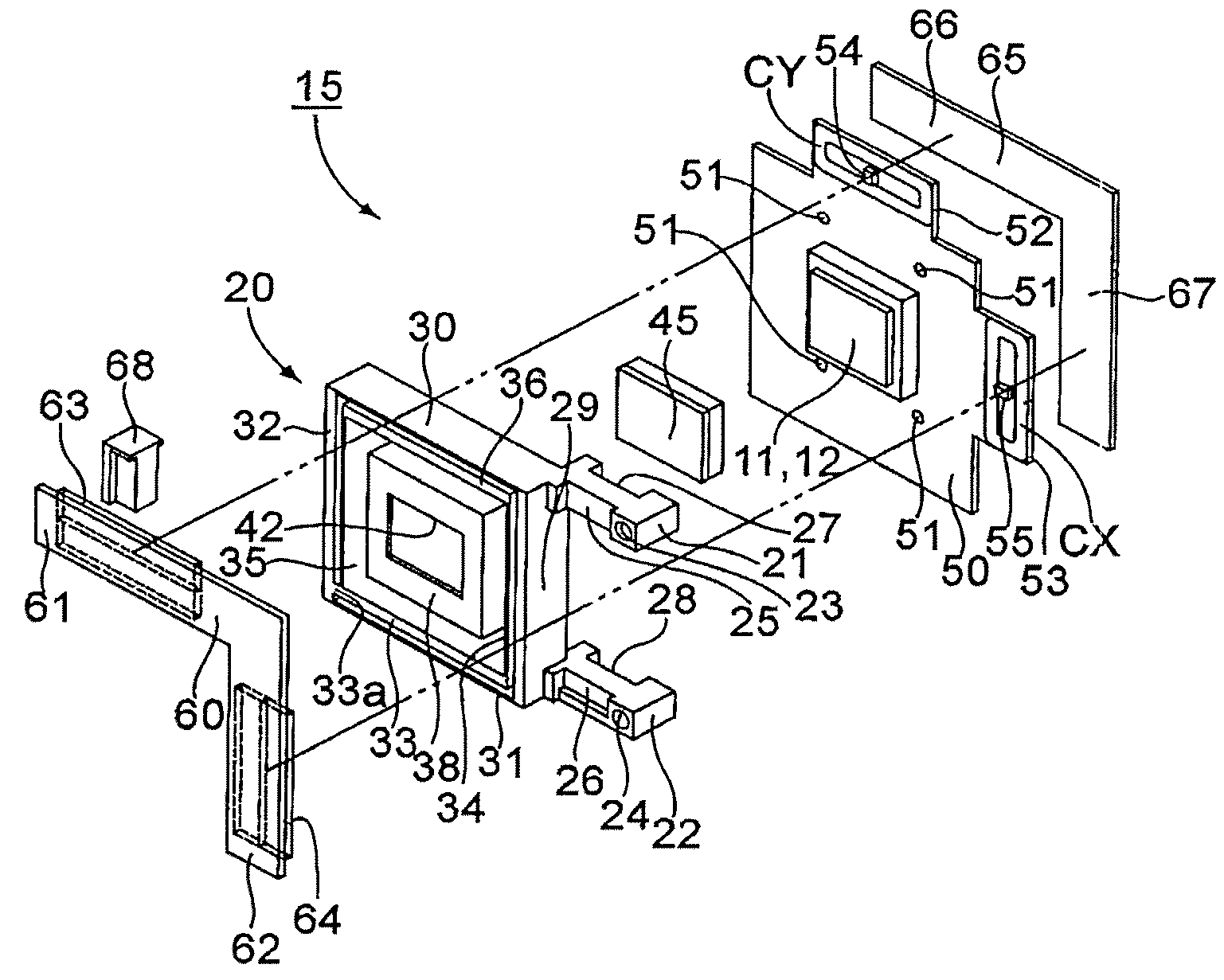
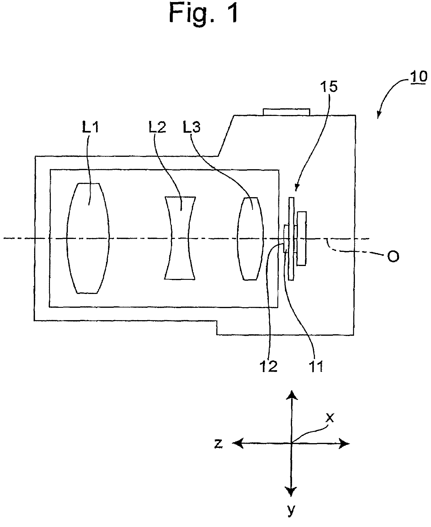
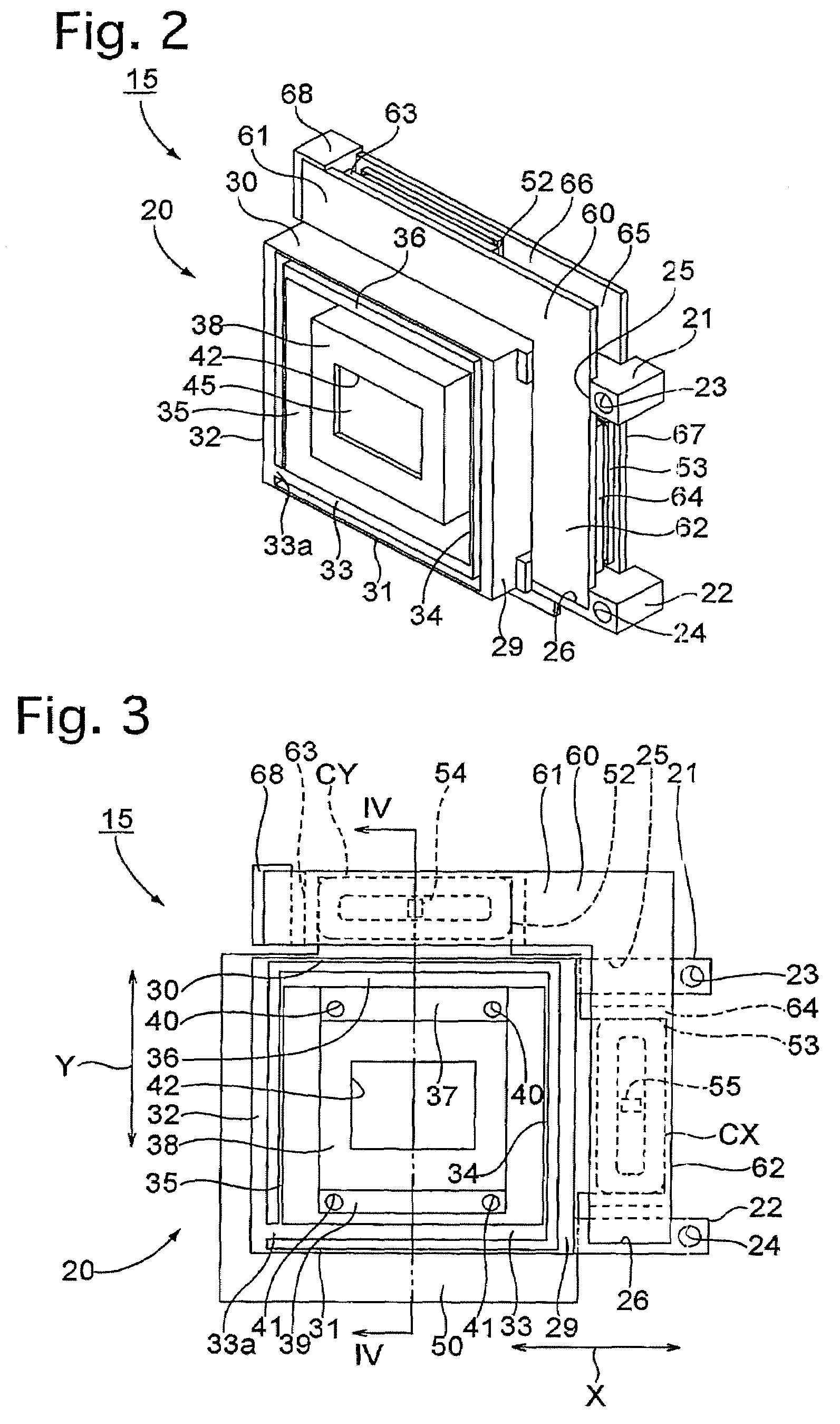
[0047]An embodiment of a camera shake correction apparatus (anti-shake system / image stabilizer) according to the present invention will be hereinafter discussed with reference to FIGS. 1 through 7. The camera shake correction apparatus 15 is incorporated in a digital camera 10 (stationary body) as shown in FIG. 1.

[0048]As shown in FIG. 1, the digital camera 10 is provided therein with a photographing optical system including a plurality of lenses L1, L2 and L3. An image pickup device 11 is provided behind the lens L3. The image pickup device 11 is provided with an imaging surface (image-forming plane) 12 which is perpendicular to an optical axis O of the photographing optical system. The position of the imaging surface 12 in the direction of the optical axis O (optical axis direction) is located on an image plane of the photographing optical system. In the present embodiment, the image pickup device 11 is secured to the camera shake correction apparatus 15 that is incorporated in th...


PUM


Abstract

An anti-shake system includes a movable portion to which an optical element is mounted; a support member which holds the movable portion in a manner to allow the movable portion to move freely in directions orthogonal to an optical axis; and a drive system which drives the movable portion in the directions orthogonal to the optical axis. A natural frequency of the movable portion that originates from the movable portion and the support member is set within the range of frequencies of shaking of an apparatus equipped with the anti-shake system which is caused by hand shake.

Description

BACKGROUND OF THE INVENTION[0001]1. Field of the Invention[0002]The present invention relates to an anti-shake system which moves a movable member holding a correction lens or an image pickup device in directions orthogonal to an optical axis to counteract the effects of shaking of an apparatus (e.g., camera) equipped with the anti-shake system which is caused by hand shake.[0003]2. Description of the Prior Art[0004]Various types of digital cameras including an anti-shake system have been developed in recent years. An anti-shake system moves a correction optical system (e.g., a correction lens), which is positioned at some midpoint in a photographing optical system, or an image pickup device in a plane orthogonal to an optical axis of the photographing optical system to offset image shake caused by hand shake. The correction optical system or the image pickup device has its own natural frequency (natural vibration frequency) at which the correction optical system or the image pickup...

Claims


Application Information

Patent Timeline
Patent Type & Authority Patents(United States)
IPC IPC(8): G03B17/00H04N5/228
CPCG03B5/00
Inventor ENOMOTO, SHIGEO
Owner RICOH IMAGING COMPANY
Learn More