
Universal support and vibration isolator

a universal support and vibration isolation technology, applied in the field of supports, can solve the problems of unfavorable use of the system, damage to the piping system or the anchorage, and noise generated by such vibrations may be irritating to people within the building, so as to reduce the inventory

Inactive Publication Date: 2009-03-10
SEICON
View PDF22 Cites 48 Cited by
  • Summary
  • Abstract
  • Description
  • Claims
  • Application Information

AI Technical Summary

Benefits of technology

[0013]The present invention offers numerous advantages. The support is easily attached to a pipe or other object and can be used to secure an object as well as isolate vibration occurring in or transmitted by the object. One or more supports may be used for a single object to ease of installation, reduce inventory, or accommodate the configuration of a supported object. The frequency response of the support may be adjusted to the particular vibration conditions associated with the object. The support allows for adjustment of the clamping pressure that the support holds the object with. The support also automatically centers an object when the support members are engaged. The orientation of an object may be adjusted with respect to the frame once the object is secured by the support, a feature that is not available in other supports. In addition, the support may secure a sliding or rotating object while the support independently slides or rotates within an enclosure.

Problems solved by technology

Such piping systems are subject to various forces that may cause movement or vibration in the pipes and damage the piping system or the anchors that hold the pipes.
The noise generated by such vibration may be irritating to people within the building.
Other systems in building, commercial installations, and the like, also may be subject to forces that may cause unwanted or damaging movement or vibration of the systems.
Conversely, if the systems include nonstatic elements, such as a rotating drill or drive shaft, the systems may themselves generate forces that cause unwanted or damaging movement or vibration of the structures that anchor or retain the systems in position.

Method used


Image

  • Universal support and vibration isolator
  • Universal support and vibration isolator
  • Universal support and vibration isolator

Examples


Embodiment Construction

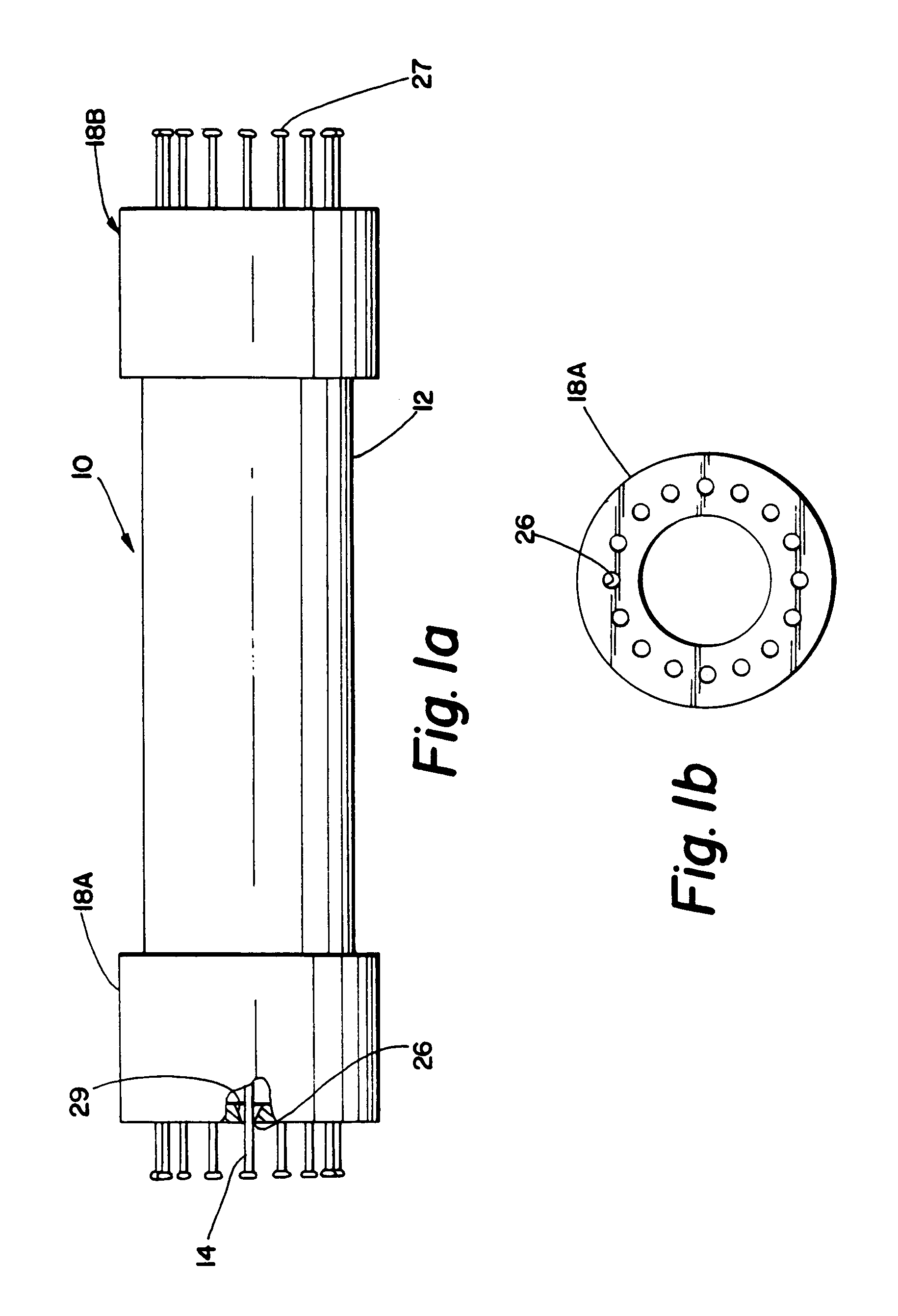
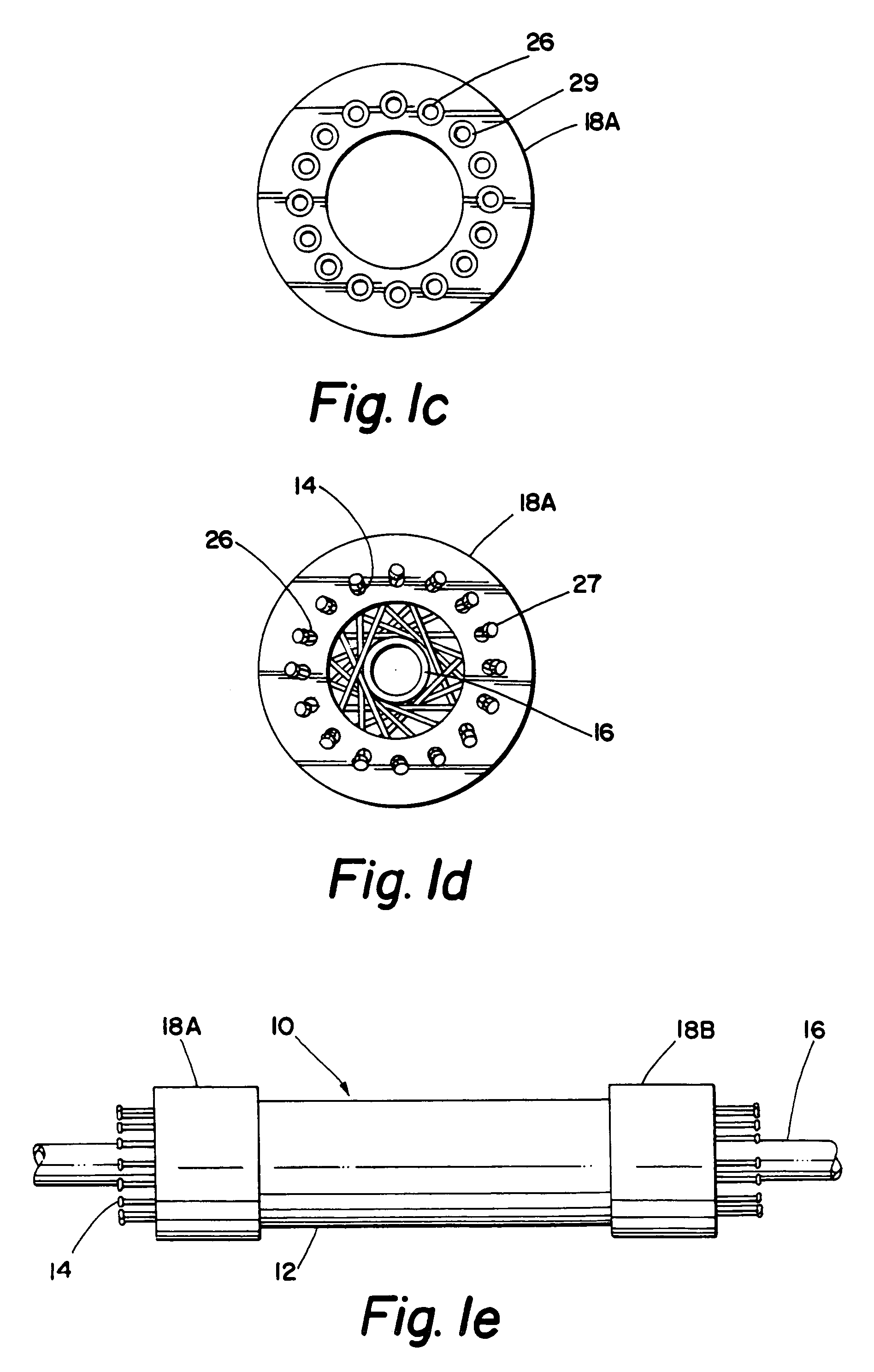
[0071]As illustrated in FIGS. 1A-20, a support 10 is provided for supporting pipes, clamping pipes, isolating pipes from the environment, and / or isolating shock and vibration from pipes. While the illustrated embodiments of the present invention are particularly adapted for use with pipes, it is noted that the present invention can be used with any other object or group of objects placed within the support 10, such as, for example, distribution means, electric cable, and motors or portions of motors. One or multiple supports 10 may be used to support an object, clamp an object, and / or isolate vibration associated with an object. It is understood that the object may be provided with bearing means so that it may rotate and that the support frame may be provided with rotating, slidable means so that it might itself rotate and slide within an enclosing structure. Other embodiments and design variations will be readily apparent to those skilled in the art given the benefit of this disclo...


PUM


Abstract

A pipe support is provided that includes a frame capable of being placed around an existing pipe and a plurality of support members within the frame. The frame is a hollow cylinder that includes two connectable halves divided along the diameter of the hollow cylinder. The pipe support includes two bearing rings connected to the frame for supporting each of the plurality of members at a minimum of two contact points. Each of the two bearing rings include bearing points for each support member arranged in a cylindrical pattern concentric with the hollow cylinder frame. The pipe support includes means for rotating each of the support members at a first contact point with respect to a second contact point so that the support members engage a pipe placed within the pipe support. The support members are rods that provide vibration isolation to a pipe placed within the pipe support.

Description

[0001]This application is a continuation of U.S. patent application Ser. No. 10 / 007,312, filed Nov. 10, 2001 now abandoned, which in turn claims priority under U.S. provisional patent application Ser. No. 60 / 247,290, filed Nov. 10, 2000.BACKGROUND OF THE INVENTION[0002]This invention relates to supports and, more specifically, to supports, clamps, mounting and positioning devices, protectors, and vibration isolators designed for pipes, motors, and other objects, including objects with solid cross-sections such as rotating drills and drive shafts.[0003]Piping systems in buildings and commercial installations, such as factories, refineries, and chemical plants, are often anchored to the building structure. Such piping systems are subject to various forces that may cause movement or vibration in the pipes and damage the piping system or the anchors that hold the pipes. The noise generated by such vibration may be irritating to people within the building. Some of the events that cause m...

Claims


Application Information

Patent Timeline
IPC IPC(8): F16L3/00F16F15/02F16F15/06F16L3/10F16L3/16F16L7/00F16L55/035F16L55/04
CPCF16F15/06F16L3/1016F16L3/1033F16L3/16F16L7/00F16L55/035A63B59/0092A63B60/54F16L55/00
Inventor CUNNINGHAM, JOHNROEMER, ROBERT E.BANASIK, ROBERT C.
Owner SEICON
Learn More