Load controlled battery charging device

a charging device and battery technology, applied in the direction of electric vehicles, transportation and packaging, and battery arrangement, can solve the problems of irreparably damaging the storage battery, the portable electronic device, and the structure of the charging device for use with a 12 volt dc or 24 volt dc storage battery, etc., to achieve efficient, economic, and effective recharge

Inactive Publication Date: 2009-03-03
CALDWELL LAZER
View PDF14 Cites 16 Cited by
  • Summary
  • Abstract
  • Description
  • Claims
  • Application Information

AI Technical Summary

Benefits of technology

[0012]Additionally, the load controlled battery charging device includes a load bank interconnected in the series configuration of the electrical charging circuit. The load bank is structured to draw a substantially constant electrical current from the power supply within a predetermined electrical current range. More in particular, the predetermined electrical current range corresponds to the range of voltage output capac

Problems solved by technology

While these devices may be effective in recharging such batteries, they are also typically specialized devices and may only be utilized for a small range of rechargeable storage batteries having the same or similar voltage output capacities.
For example, a charging device structured for use with a 12 volt DC or 24 volt DC storage battery, such as may be used in an automobile, truck, or marine vehicle, are not readily adaptable for use with smaller storage batteries, such as the “AAA”, “C”, or “D” type batteries utilized in many portable electronic devices, much less the rechargeable storage batteries utilized to power the smallest portable electronic devices such as cellular telephones, PDA's, and digital cameras, just to name a few.
Addi

Method used


Image

  • Load controlled battery charging device
  • Load controlled battery charging device
  • Load controlled battery charging device

Examples


Embodiment Construction

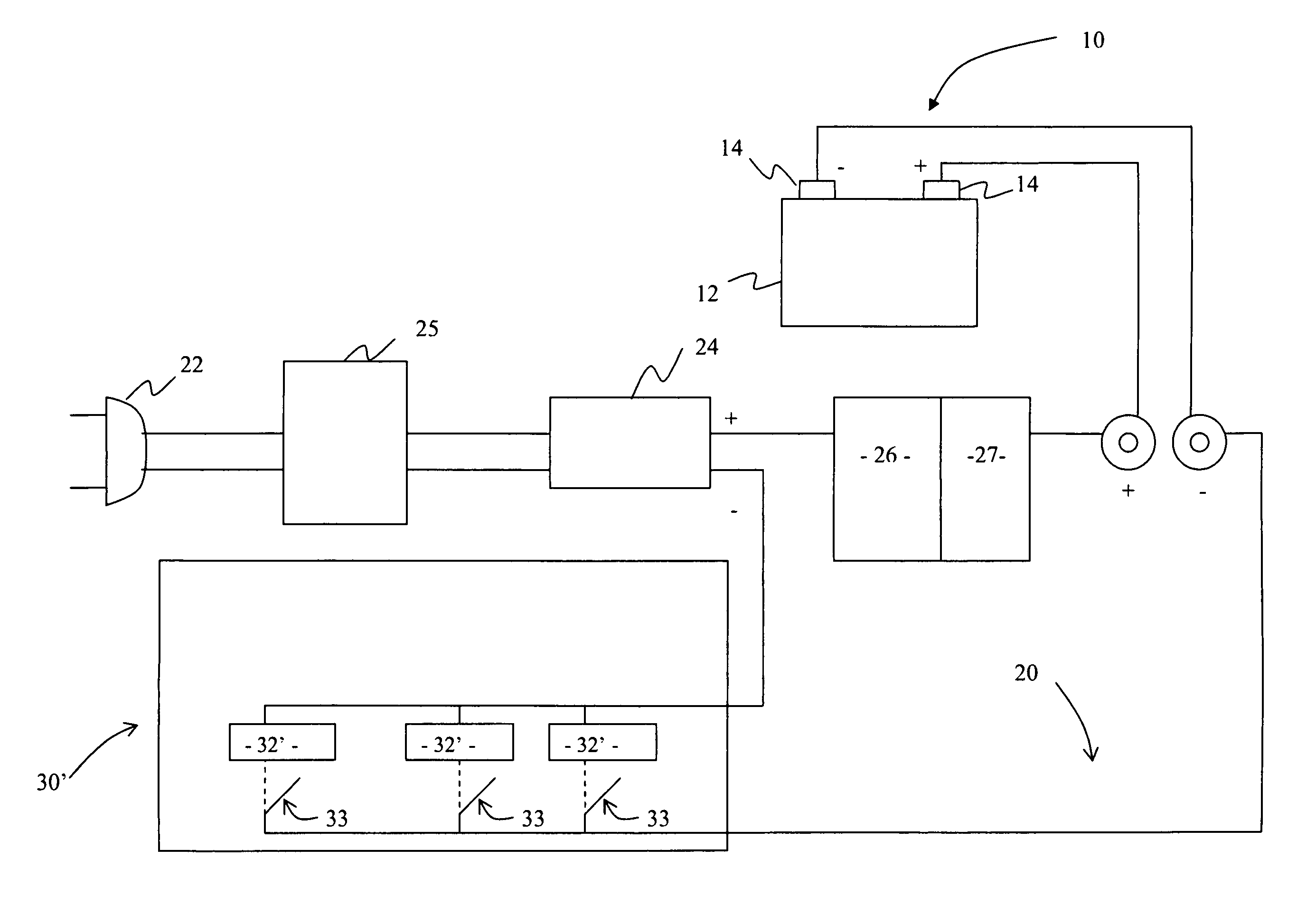
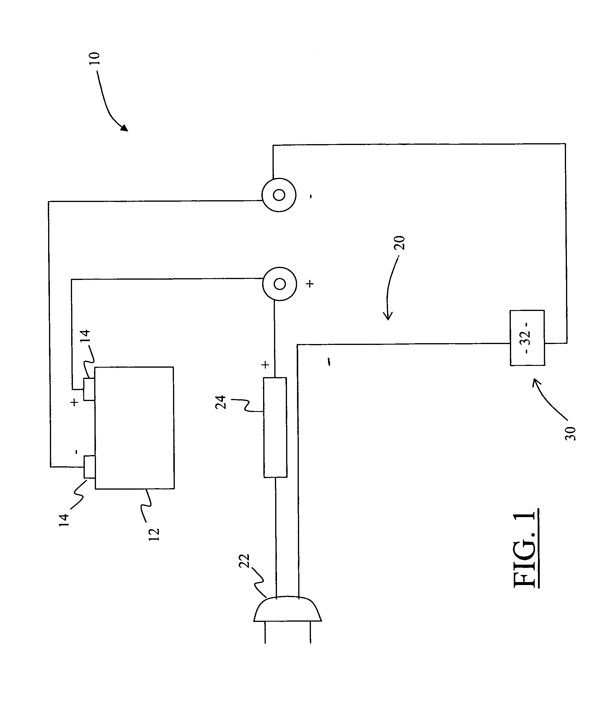
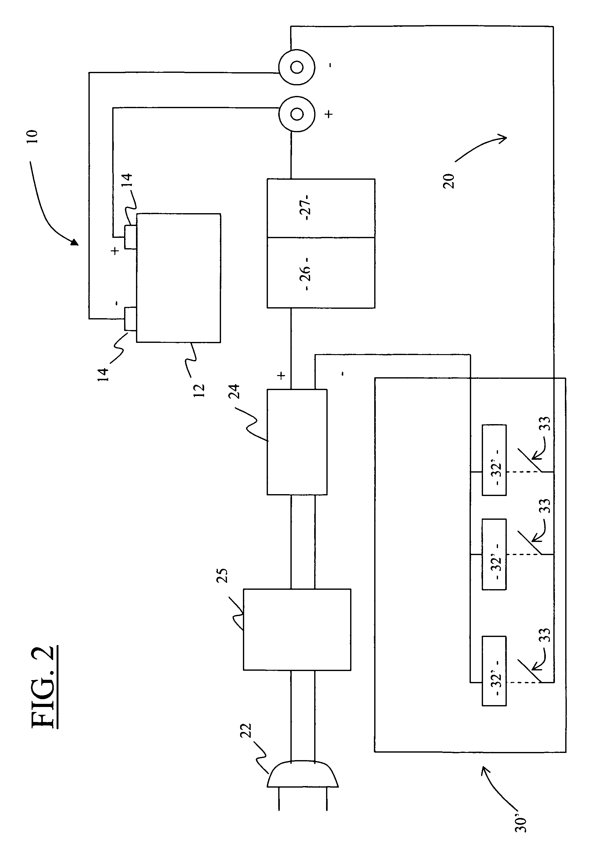
[0019]As stated above, the present invention is directed to a load controlled battery charging device, generally as shown in the figures as at 10. More in particular, the load controlled battery charging device 10 of the present invention is structured so as to efficiently, effectively, and economically apply a charge to a rechargeable storage battery 12.

[0020]The load controlled battery charging device 10 includes an electrical charging circuit 20 having an input connection 22 structured to receive power from a power supply. In at least one embodiment, the power supply may comprise a standard 110 or 220 volt household electrical power supply, in which case, the input connector 22 comprises a standard 110 or 220 volt plug. Further, in this embodiment, the electrical charging circuit 20 is structured to convert the alternating current household power supply to a direct current charging supply for application to the rechargeable storage battery 12, as discussed in greater detail below...


PUM


Abstract

A load controlled battery charging device is provided which is structured to apply an electrical charge to a plurality of rechargeable storage batteries having a wide range of voltage output capacities. The device includes an electrical charging circuit having an input connection to a power source to provide the power required to permit recharging the batteries. The load controlled charging device also includes a load bank structured to draw a substantially constant electrical current from the power input, and may include a rectifier to convert an alternating current power supply to a direct current to be applied to the rechargeable storage batteries. Additionally, the load controlled battery charging device includes a charging current output connection structured to interconnect the electrical charging circuit to the rechargeable storage battery, at least during the charging operation.

Description

CLAIM OF PRIORITY[0001]The present application is a continuation-in-part patent application which claims priority to the non-provisional patent application having Ser. No. 10 / 877,185, filed on Jun. 28, 2004, now abandoned which is incorporated herein by reference.BACKGROUND OF THE INVENTION[0002]1. Field of the Invention[0003]The present invention is directed to a load controlled battery charging device structured to apply a charge to a rechargeable storage battery having any one of a wide range of voltage output capacities. The load controlled battery charging device utilizes a load bank disposed in series with a power supply and a rechargeable storage battery, wherein a charging current applied to the rechargeable storage battery is controlled via a substantially constant electrical current drawn by the load bank.[0004]2. Description of the Related Art[0005]As the number of portable electronic devices available for communication, entertainment, and even transportation become incre...

Claims


Application Information

Patent Timeline
IPC IPC(8): H02J7/00H02J7/02H02J7/04
CPCH02J7/0013H02J7/0068
Inventor CALDWELL, II, WILLIAM S.
Owner CALDWELL LAZER
Why Eureka
Try Eureka