
Gas turbine rotor blade

a technology of rotor blades and turbine blades, which is applied in the direction of blade accessories, leakage prevention, machines/engines, etc., can solve the problems of destroying blades and turbines, and configurations that are not mechanically satisfactory, and achieve the effect of being convenient and effectiv

Active Publication Date: 2009-03-03
SN DETUDE & DE CONSTR DE MOTEURS DAVIATION S N E C M A
View PDF11 Cites 11 Cited by
  • Summary
  • Abstract
  • Description
  • Claims
  • Application Information

AI Technical Summary

Benefits of technology

The invention provides a solution to a problem of high temperature gradients and resulting cracks at the connection between the trailing edge and the platform of a blade. The solution involves cooling the connection zone between the trailing edge and the platform by limiting the temperature gradient between the connection zone and the stiffener. This is achieved by forming a cavity in the stiffener that is connected to a cooling fluid outlet orifice opening under the platform. The cooling fluid flows through the cavity without disturbing the flow of gas leaving the blade. The invention is cost-effective and effective in reducing the risk of cracks forming at the connection between the trailing edge and the platform.

Problems solved by technology

This connection zone is thus remote from cooling air and it is in contact with the hot gas flowing through the turbine, so it is subjected to intense thermal stresses, leading to the formation of cracks that can destroy the blade and also the turbine.
Proposals have already been made to cool this connection zone by a flow of air leaving through orifices formed in the platform and opening out into the suction surface, but that configuration is not mechanically satisfactory.

Method used


Image

  • Gas turbine rotor blade
  • Gas turbine rotor blade
  • Gas turbine rotor blade

Examples


Embodiment Construction

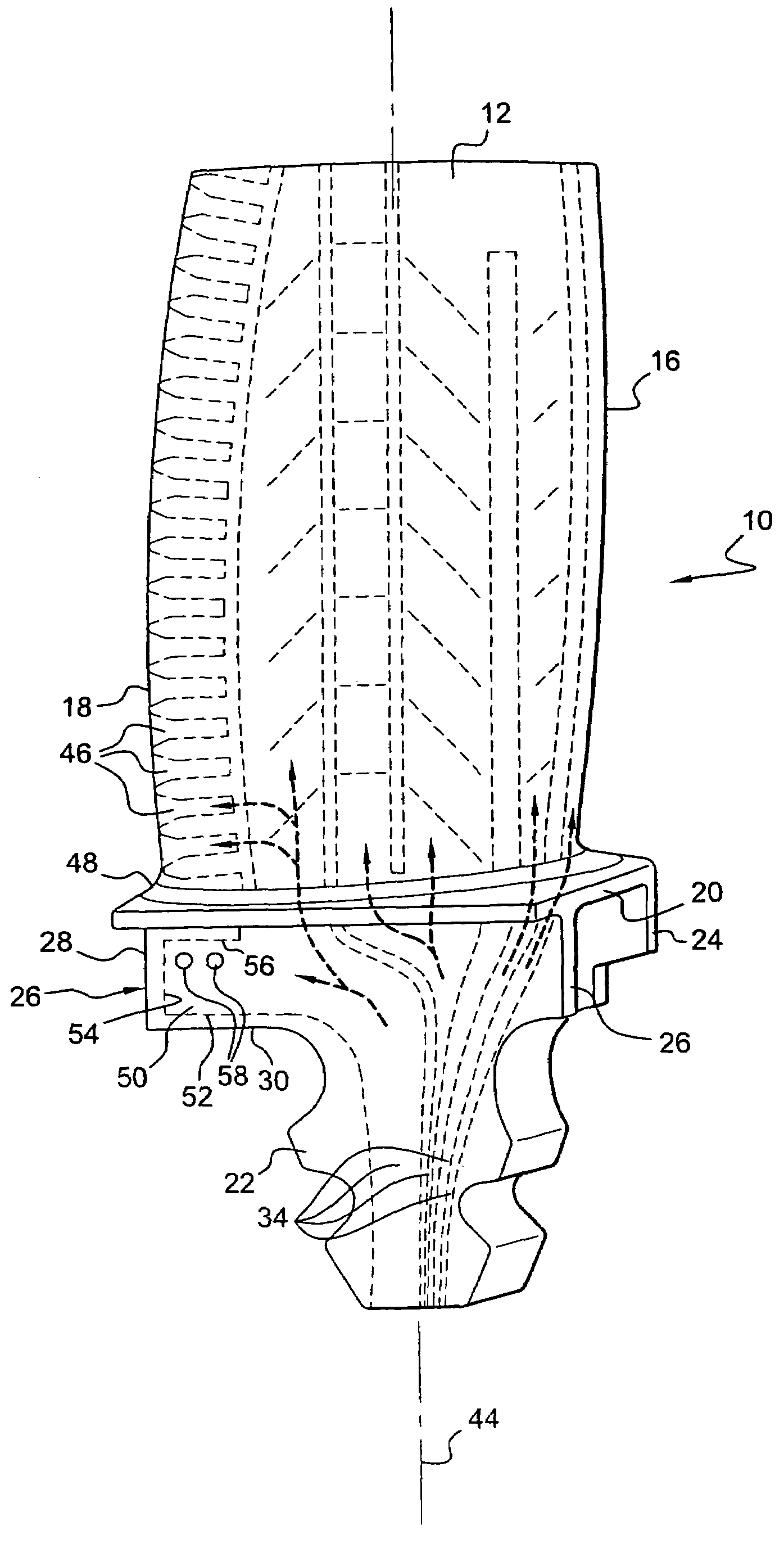
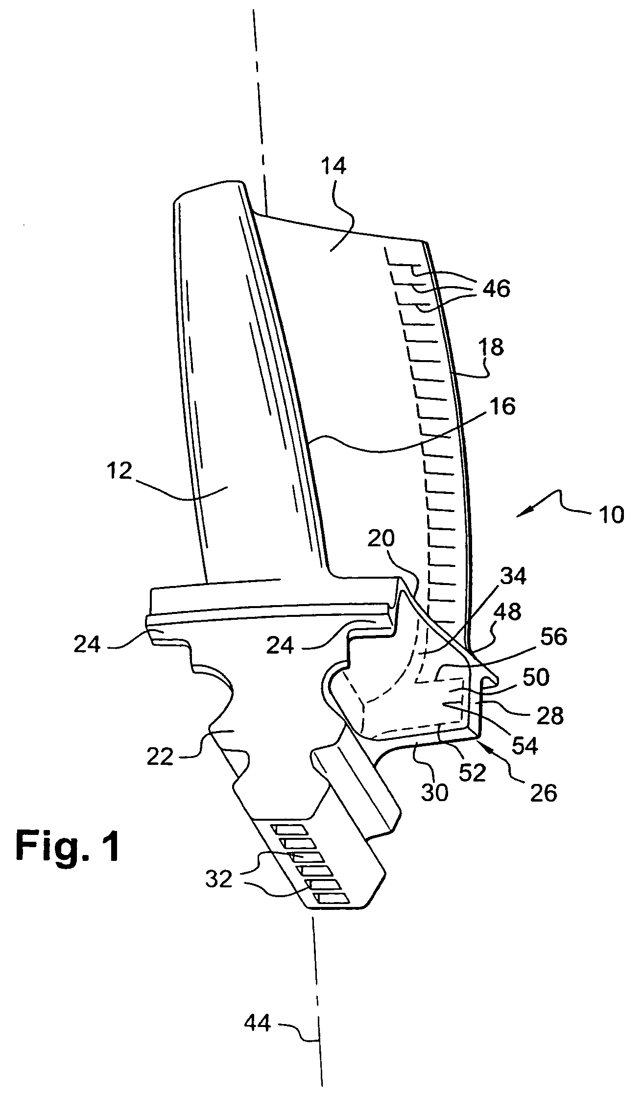
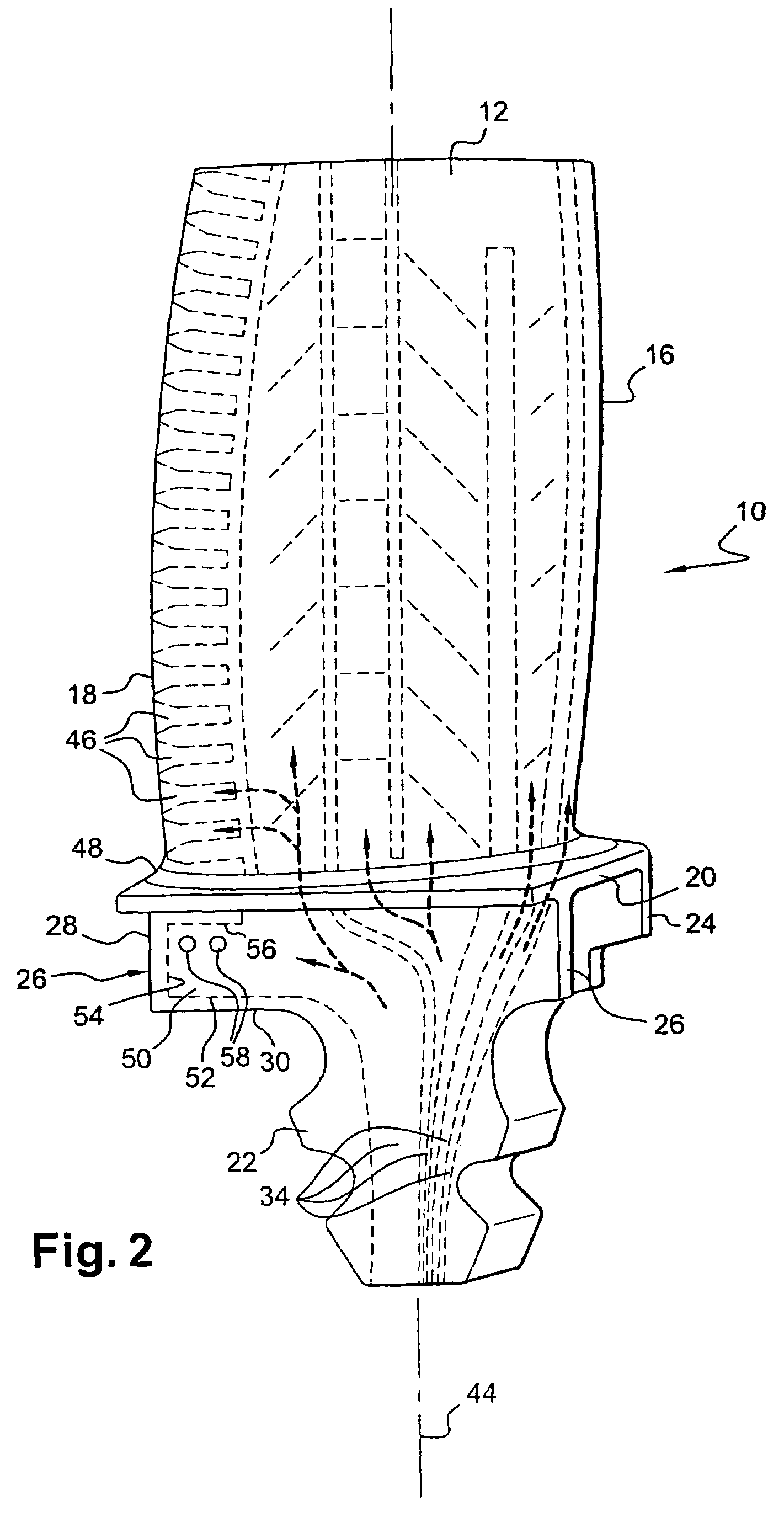
[0019]FIGS. 1 and 2 show a blade 10 of a high pressure stage of a gas turbine, and in particular of a turbojet. This blade 10 comprises an airfoil formed with a suction or convex outer surface 12 and with a pressure or concave inner surface 14, which surfaces are interconnected at their upstream ends by a leading edge 16 and at their downstream ends by a trailing edge 18, where “upstream” and “downstream” are relative to the flow direction of the gas flowing through the turbine.

[0020]The blade is connected via a substantially rectangular transverse platform 20 to a blade root 22 whereby the blade 10 is mounted on a disk (not shown) of the rotor of the gas turbine, by engaging said root 22 in a cavity of complementary shape in the periphery of the rotor disk. By means of this male / female engagement, which is of the Christmas tree type in the example shown, the blade 10 is held radially on the rotor disk. Other means are provided for preventing the root 22 of the blade 10 from moving ...


PUM


Abstract

A rotor blade for a gas turbine, in particular a turbojet, the blade comprising an airfoil, a platform connecting the airfoil to a blade root and having at least one stiffener extending under the downstream portion of the platform, together with means for cooling the blade by a flow of cooling fluid in ducts formed in the blade and in a cavity formed in the stiffener substantially in register with the trailing edge of the blade, and including outlet orifices facing downstream.

Description

[0001]The present invention relates to a rotor blade for a gas turbine, in particular a high pressure turbine of a turbojet.BACKGROUND OF THE INVENTION[0002]In known manner, a gas turbine rotor blade comprises an airfoil formed with a suction or convex outer surface and with a pressure or concave inner surface, which surfaces are interconnected at their upstream ends by a leading edge and at their downstream ends by a trailing edge, where “upstream” and “downstream” are relative to the gas flow direction. The airfoil is connected by a platform to a blade root of the dovetail, Christmas tree, or similar type for insertion in a corresponding cavity of a rotor disk of the gas turbine. At least one reinforcing web, referred to as a “stiffener”, is formed at the downstream end of the platform on its side opposite from the airfoil and it extends transversely, being connected to the blade root.[0003]The blade also includes cooling means whereby a fluid such as air flows through ducts that ...

Claims


Application Information

Patent Timeline
Patent Type & Authority Patents(United States)
IPC IPC(8): F01D5/08
CPCF01D5/081F01D5/187F05B2240/801F05D2240/81
Inventor BOURY, JACQUES AUGUSTE AMEDEEJUDET, MAURICE GUY
Owner SN DETUDE & DE CONSTR DE MOTEURS DAVIATION S N E C M A
Learn More