
Water submersible electronics assembly and methods of use

a technology of electronics and submerged water, applied in underwater equipment, special-purpose vessels, instruments, etc., can solve the problems of low cost of widespread persistent monitoring by submarines, and inability to reliably detect underwater conditions, etc., to achieve negative buoyancy

Inactive Publication Date: 2009-02-24
IROBOT CORP
View PDF16 Cites 51 Cited by
  • Summary
  • Abstract
  • Description
  • Claims
  • Application Information

AI Technical Summary

Benefits of technology

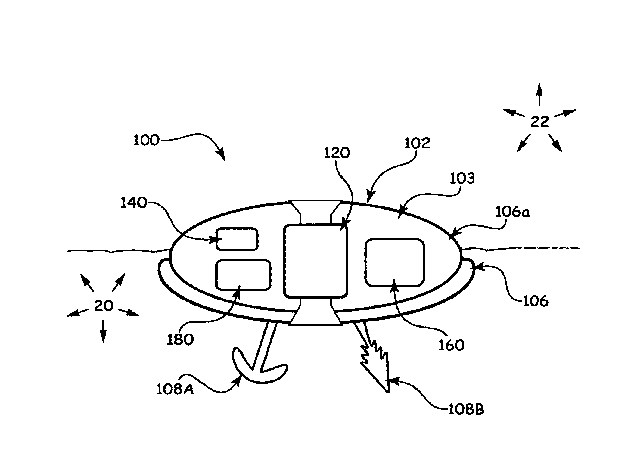
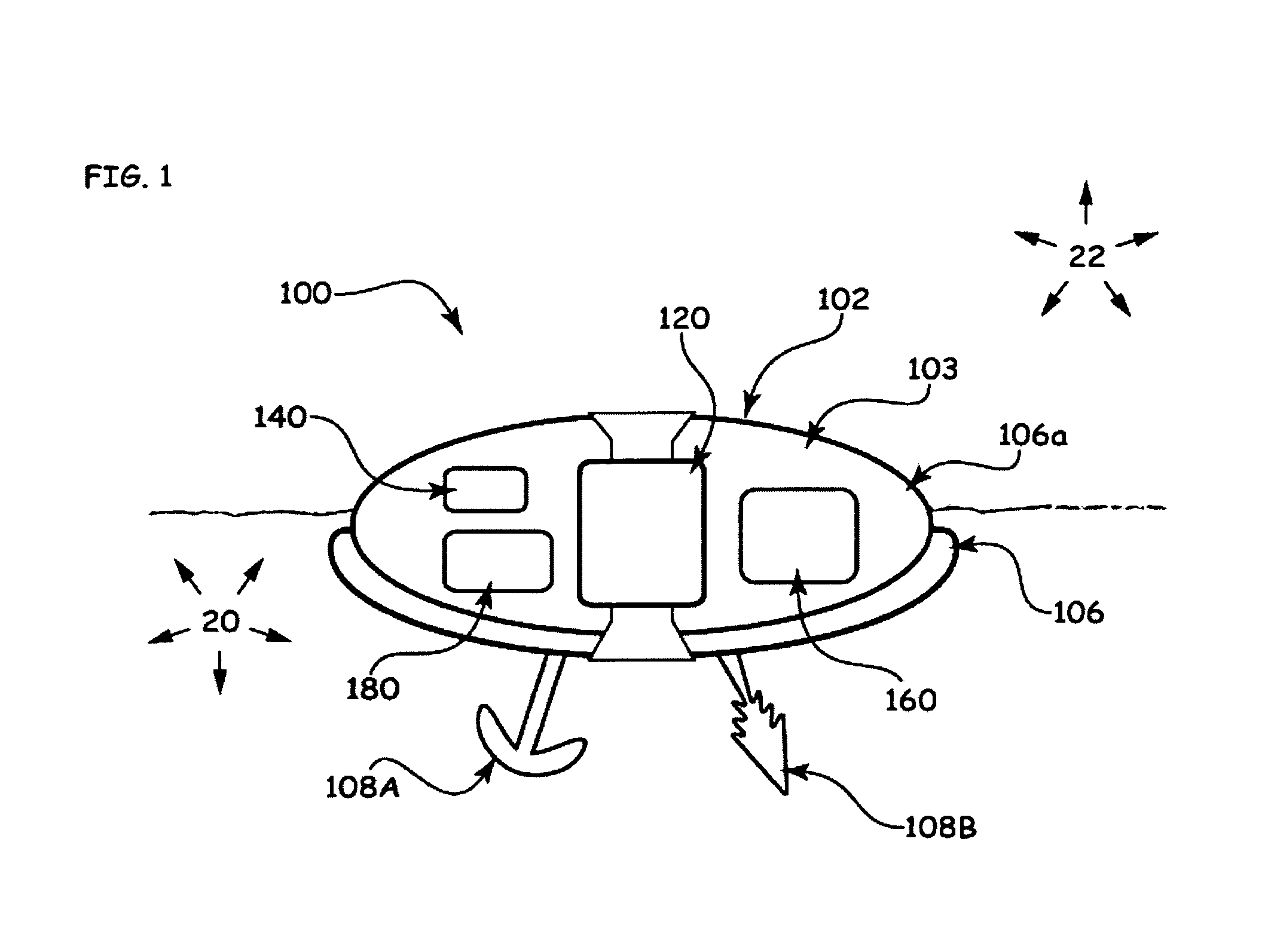
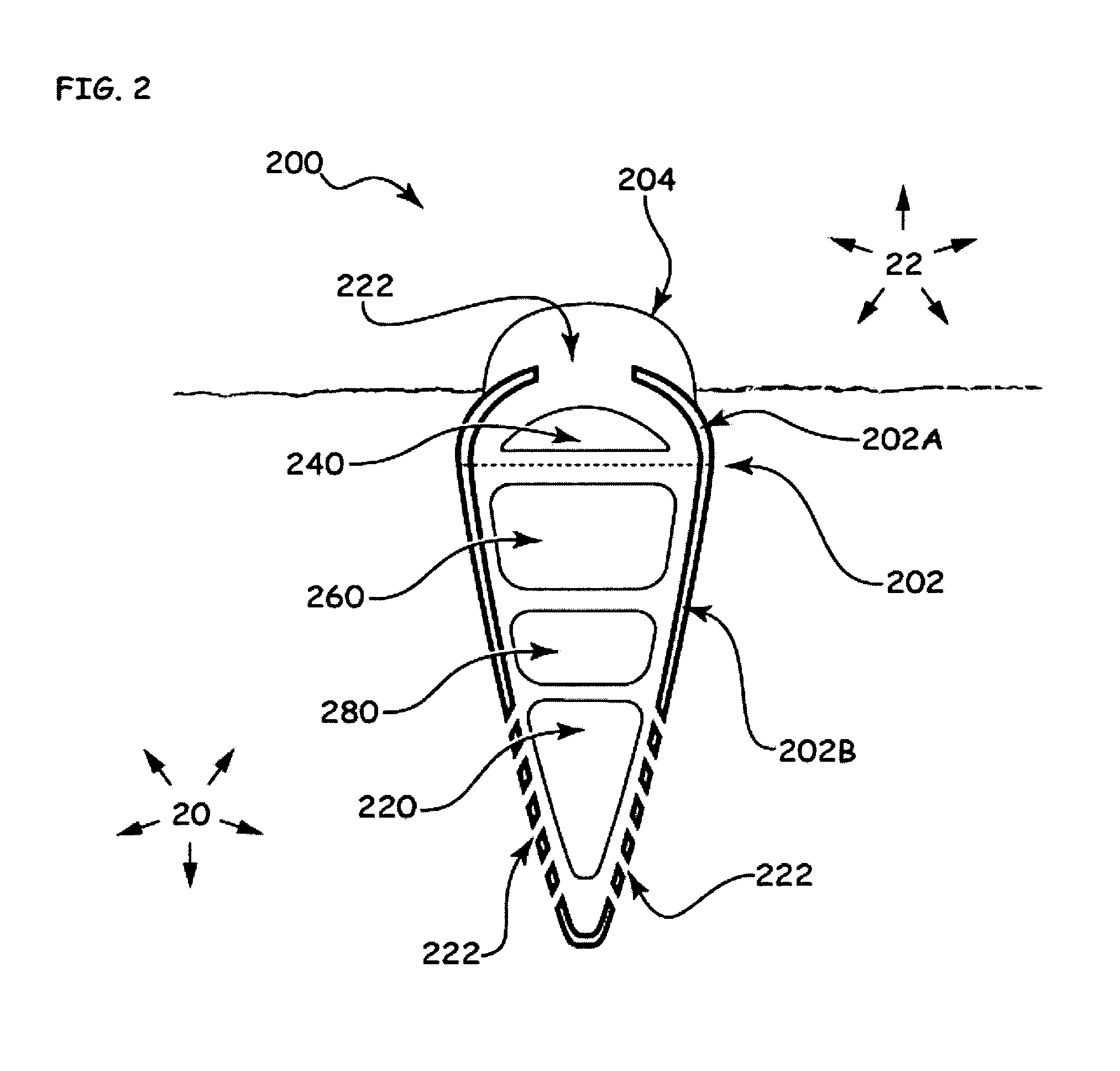
The present invention is about a submersible electronics device that can be used in a body of water and a substratum floor below the water. The device has a housing, an operational electronics system, and a mobility system. The mobility system can be used to move the housing into the substratum to at least partially bury it or move it out of the substratum. The device can also have a sensor system to sense the environment and communicate with another device. The device can be used for various applications such as communication and sensing. The technical effects of the invention include improved mobility and flexibility in navigating the substratum floor, as well as better communication and sensing capabilities.

Problems solved by technology

Access to some regions of littoral seas for such purposes may, however, be denied and / or the cost of widespread persistent monitoring by submarine may be prohibitive or unsustainable.
Seafloor electronics devices are, however, often at risk of disturbance or damage by currents or by equipment (e.g., fishing nets) and other objects moving over the seafloor.
Sensors that are easily dislodged or damaged are clearly undesirable for persistent or undetected monitoring.

Method used


Image

  • Water submersible electronics assembly and methods of use
  • Water submersible electronics assembly and methods of use
  • Water submersible electronics assembly and methods of use

Examples


Embodiment Construction

[0032]The present invention now will be described more fully hereinafter with reference to the accompanying drawings, in which illustrative embodiments of the invention are shown. In the drawings, the relative sizes of regions or features may be exaggerated for clarity. This invention may, however, be embodied in many different forms and should not be construed as limited to the embodiments set forth herein; rather, these embodiments are provided so that this disclosure will be thorough and complete, and will fully convey the scope of the invention to those skilled in the art.

[0033]It will be understood that when an element is referred to as being “coupled” or “connected” to another element, it can be directly coupled or connected to the other element or intervening elements may also be present. In contrast, when an element is referred to as being “directly coupled” or “directly connected” to another element, there are no intervening elements present. Like numbers refer to like elem...


PUM


Abstract

A submersible electronics device for use in a body of water and a substratum floor below the body of water includes a submersible housing, an operational electronics system, and a mobility system. The operational electronics system is mounted in and / or on the housing. The operational electronics system is adapted to communicate with another device and / or to sense at least one of a physical signal and an environmental parameter. The mobility system is selectively operable to fluidize the substratum, vibrate the housing, and / or adjust a buoyancy of the submersible electronics device to selectively move the housing into the substratum to at least partially bury the housing in the substratum and / or to selectively move the housing out of the substratum to at least partially unbury the housing from the substratum.

Description

RELATED APPLICATION(S)[0001]This application claims the benefit of and priority from U.S. Provisional Patent Application Ser. No. 60 / 705,004, filed Aug. 3, 2005, the disclosure of which is incorporated herein by reference in its entirety.STATEMENT OF GOVERNMENT SUPPORT[0002]This invention was made with support under Small Business Innovation Research (SBIR) Program No. N66604-05-C-0287 awarded by the United States Navy. The Government has certain rights in the invention.FIELD OF THE INVENTION[0003]The present invention relates to water submersible electronics devices and methods for using the same.BACKGROUND OF THE INVENTION[0004]Persistent underwater monitoring or surveillance, such as in antisubmarine warfare (ASW) or antiterrorism monitoring, typically relies on sonar sensors deployed on the seafloor or towed by surface ships or submarines. Persistent seafloor sensors today may be connected by a cable to a ship or shore station. Access to some regions of littoral seas for such pu...

Claims


Application Information

Patent Timeline
Patent Type & Authority Patents(United States)
IPC IPC(8): H04B11/00B63G8/00
CPCH04B13/02B63B22/08
Inventor VOSBURGH, FREDERICK
Owner IROBOT CORP
Learn More