Radio tag communication system
a technology of radio tag and communication system, applied in the direction of polarisation/directional diversity, mechanical actuation of burglar alarms, instruments, etc., to achieve the effect of preventing signal interferen
- Summary
- Abstract
- Description
- Claims
- Application Information
AI Technical Summary
Benefits of technology
Problems solved by technology
Method used
Image

Examples
embodiment 1
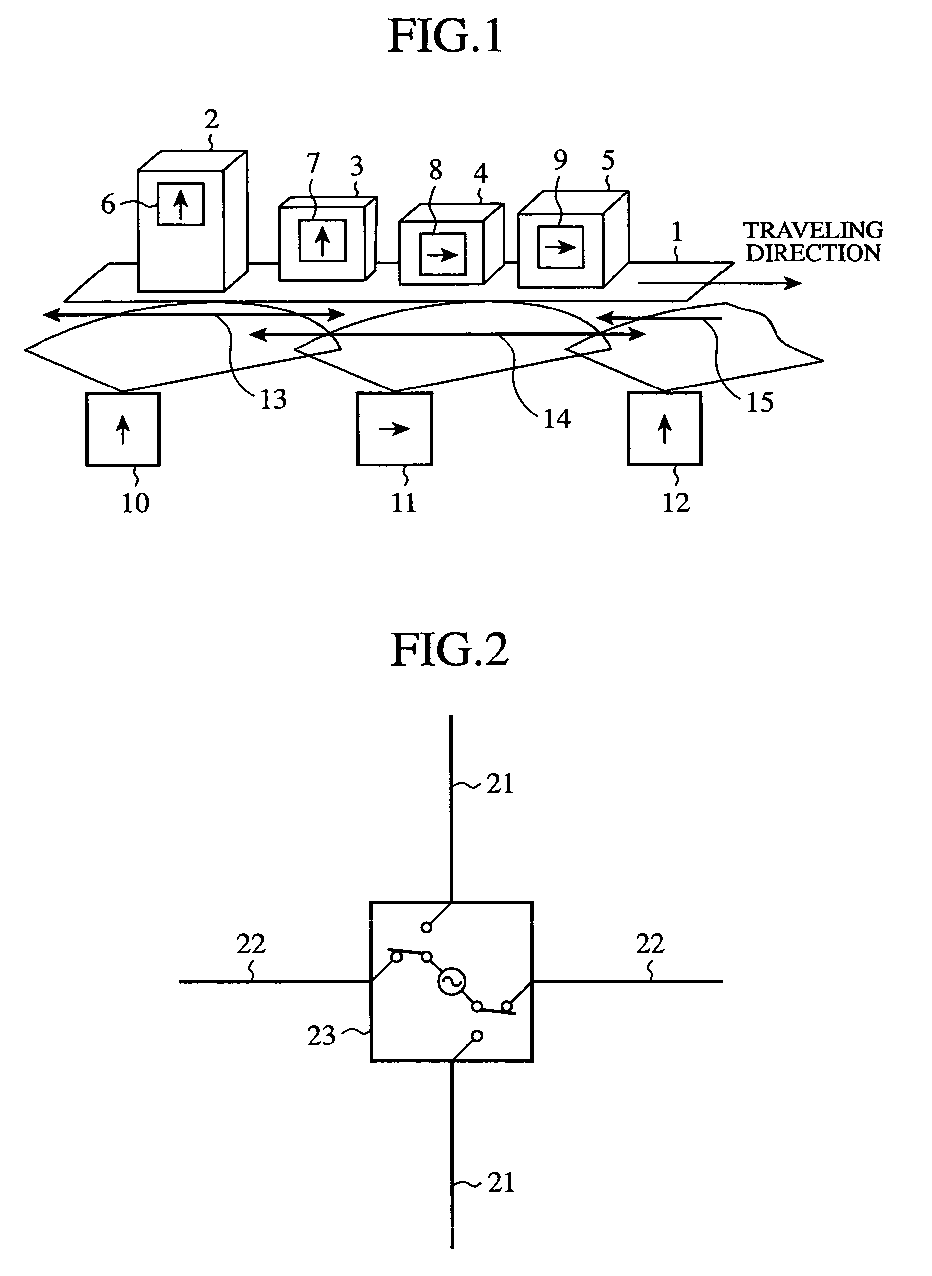
[0019]FIG. 1 is a diagram showing a configuration of a radio tag communication system of an embodiment 1 in accordance with the present invention.
[0020]In FIG. 1, a conveyor 1, which is installed on a manufacturing line, for example, one-dimensionally carries articles 2-5 on which tags 6-9 are put. In the example of FIG. 1, the articles 2-5 move toward the right.
[0021]The articles 2-5 are products in progress, for example, and can differ in size from each other.
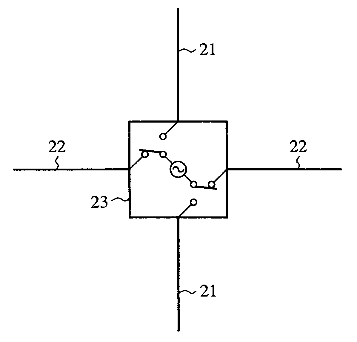
[0022]The tags 6-9, which are put on the articles 2-5, have a function of holding unique information on the articles 2-5 (such as identifying information of the articles), and a function of carrying out radio communication with RW apparatuses 10-12, which are reader / writer apparatuses. In addition, the tags 6-9 have a function of switching the polarization direction as they move on.
[0023]The RW apparatuses 10-12 are arranged one-dimensionally along the direction in which the conveyor 1 moves the articles 2-5 in such a manner ...
embodiment 2
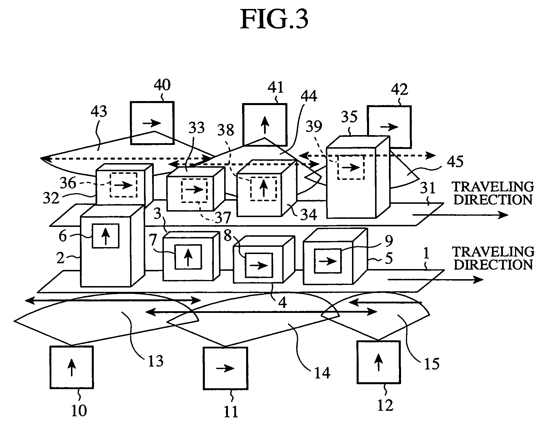
[0069]FIG. 3 is a diagram showing a configuration of a radio tag communication system of an embodiment 2 in accordance with the present invention.
[0070]In FIG. 3, the same reference numerals designate the same or like portions to those of FIG. 1, and their description will be omitted here.
[0071]A conveyor 31, which is installed on the manufacturing line, for example, one-dimensionally carries articles 32-35 on which tags 36-39 are put. In the example of FIG. 3, the conveyor 31 moves the articles 32-35 toward the right.
[0072]The articles 32-35 are products in progress, for example, and can differ in size.
[0073]The tags 36-39, which are put on the articles 32-35, have a function of holding unique information on the articles 32-35 (such as identifying information of the articles), and a function of carrying out radio communication with RW apparatuses 40-42. In addition, the tags 36-39 have a function of switching the polarization direction as they move on.
[0074]The RW apparatuses 40-42...
embodiment 3
[0080]FIG. 4 is a diagram showing a configuration of a radio tag communication system of an embodiment 3 in accordance with the present invention.
[0081]In FIG. 4, communication areas 51-54 are the communication areas of the RW apparatuses in which the polarized waves are set at a polarized wave (A); and communication areas 61-64 are the communication areas of the RW apparatuses in which the polarized waves are set at a polarized wave (B) orthogonal to the polarized wave (A).
[0082]The present embodiment 3 expands the movement of the articles of the foregoing embodiment 1 to two dimension. It supposes logistics management of the articles moving on the ground in a factory.
[0083]The communication areas 51-54 and 61-64 represent communication areas on the ground of a plurality of RW apparatuses that are fixed to the ceiling but are not shown. The communication areas with different reference numerals are communication areas of different RW apparatuses.
[0084]The polarized waves of the RW a...
PUM
 Abstract
Description
Claims
Application Information
 - R&D
- Intellectual Property
- Life Sciences
- Materials
- Tech Scout
- Unparalleled Data Quality
- Higher Quality Content
- 60% Fewer Hallucinations
Browse by: Latest US Patents, China's latest patents, Technical Efficacy Thesaurus, Application Domain, Technology Topic, Popular Technical Reports.
© 2025 PatSnap. All rights reserved.Legal|Privacy policy|Modern Slavery Act Transparency Statement|Sitemap|About US| Contact US: help@patsnap.com