
Image scanning system and method for scanner

a scanning system and scanner technology, applied in the field of image scanning system and scanner, can solve the problems affecting so as to achieve the effect of increasing the scanning efficiency of the scanner

Active Publication Date: 2009-02-17
INTELLECTUAL VENTURES I LLC
View PDF14 Cites 4 Cited by
  • Summary
  • Abstract
  • Description
  • Claims
  • Application Information

AI Technical Summary

Benefits of technology

"This patent describes an image scanning system and method that offers calibration parameters without performing calibration process, which improves scanning efficiency of the scanner. The system performs pre-scanning calibration before scanning and uses the obtained calibration parameter as the calibration basis for subsequent scanning. The system includes a transparent holding board, an optical chassis, and a control module. The calibration parameters are stored in the control module's memory, which allows the scanner to directly perform scanning without the need of doing calibration or calculating the calibration parameter every time, resulting in better scanning quality and increased efficiency."

Problems solved by technology

However, the scanner usually has to proceed a calibration process before performing the scanning operation.
Although the calibration process may enable the scanner to get a better scanning quality for every scanning operation, the calibration process takes a lot of time.
Hence the calibration process takes a relatively large portion of the total scanning time.
When the scanner is used for scanning a great amount of document, time being spent and wasted on calibration becomes significant.

Method used


Image

  • Image scanning system and method for scanner
  • Image scanning system and method for scanner
  • Image scanning system and method for scanner

Examples


first embodiment

[0025]Referring to FIG. 2B the process flow of the image scanning system of this invention is illustrated. The process includes the steps of: providing a scanning object 31, using the image capturing element of the optical chassis to capture the image of the scanning object 32, using the calibration parameters stored in the memory of the control module or system file to control the image capturing element to perform calibration and compensation for the captured image 33, completing the scanning for the object 35 and repeating the step 31.

[0026]In the process flow a of a second preferable embodiment, the control module uses the Random Access Memory (RAM) for storing the calibration parameters. As the data stored in the RAM will be cleared and lost after the scanner is power off, in this embodiment every time the scanner is power on, an automatic calibration will be performed, and the most updated calibration parameters obtained in the calibration process will be stored in the RAM. Th...

second embodiment

[0027]Referring to FIG. 3 the process flow of the second embodiment is illustrated. The process includes the steps of: performing a pre-scanning process and calculating the calibration parameters 41, providing a scanning object 42, using the image capturing element of the optical chassis to capture the image of the scanning object 43, using the calibration parameters stored in the memory of the control module or system file to control the image capturing element to perform calibration and compensation for the captured image 44, completing the scanning for the object 45 and repeating the 42.

third embodiment

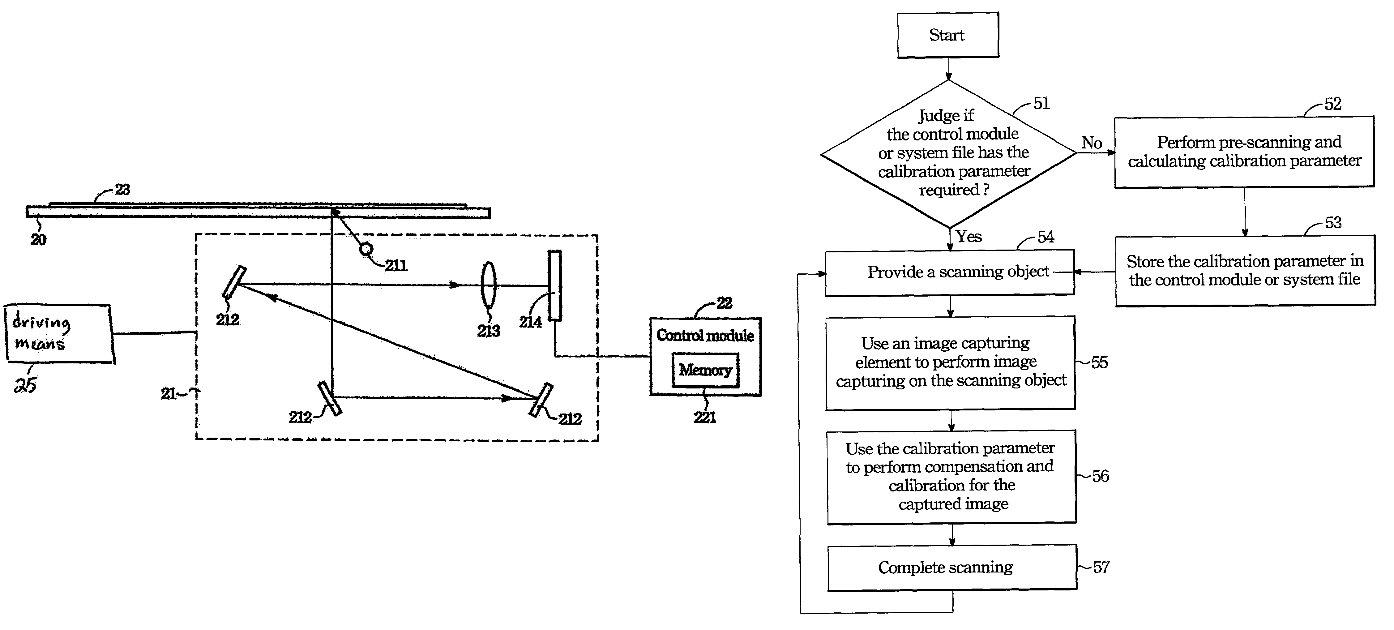
[0028]Before proceeding scanning, the scanner of this invention may also determine if the control module or system file has the required calibration parameters. If the outcome is positive, the scanning operation will be directly executed. Otherwise a pre-scanning operation will be performed and calculation of the calibration parameters for the scanner will be done. Details will be described in the third embodiment shown in FIG. 4.

[0029]The process includes the steps of: determining if the control module or system file has the calibration parameters required 51; if negative, perform pre-scanning and calculate the calibration parameters 52 and store the obtained calibration parameters in the control module or system file 53; if positive, provide a scanning object 54; using the image capturing element of the optical chassis to capture the image of the scanning object 55, using the calibration parameters stored in the memory of the control module or system file to control the image capt...


PUM


Abstract

An image scanning system and method for a scanner that stores calibration parameters of the scanner in the memory of a control module or a selected system file. The image capturing element directly performs image capturing on the scanning object and through the calibration parameters to perform compensation and calibration process for the captured image such that the scanner needs no pre-scanning or only one pre-scanning to obtain the calibration parameter from empirical value thereby to directly perform image scanning on the scanning object.

Description

FIELD OF THE INVENTION[0001]This invention relates to an image scanning system and for scanner and particularly a system and method that is capable of completing image scanning image rapidly without a pre-scanning process or one pre-scanning image scanning process.BACKGROUND OF THE INVENTION[0002]Optical scanner is a computer peripheral device that employs photoelectric conversion principle to convert scanning object image to digital data. The scanning method mainly includes projecting a linear light source on the scanning object, using an image capturing element to capture the image reflecting from the scanning object, then employing photoelectric conversion principle to convert the object image to digital signals for output.[0003]Referring to FIG. 1A, a conventional optical scanner consists of a document holding board 10 for holding a scanning object 11 thereon which is generally a flat document, and an optical chassis 12 constructed in a modular manner which consists of a linear ...

Claims


Application Information

Patent Timeline
Patent Type & Authority Patents(United States)
IPC IPC(8): H04N1/00H04N1/04H04N1/46
CPCH04N1/00795H04N1/00819H04N1/0097
Inventor LIU, CATHY
Owner INTELLECTUAL VENTURES I LLC
Learn More