
Paper sheet storage and payout device

a paper sheet and paper sheet technology, applied in the direction of article separation, thin material processing, instruments, etc., can solve the problems of large change in the angle of the separation member with respect to and the inability to perform smooth separation of paper sheets from the wrapping peripheral region of the tap

Active Publication Date: 2009-02-17
LAUREL PRECISION MACHINES
View PDF19 Cites 31 Cited by
  • Summary
  • Abstract
  • Description
  • Claims
  • Application Information

AI Technical Summary

Benefits of technology

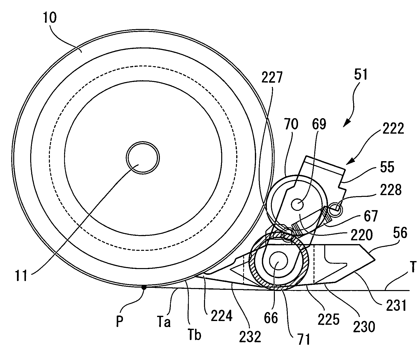
The invention is a device for storing and pouting paper sheets. It includes a mechanism for separating paper sheets from the tape that wraps around a take-up drum. The mechanism includes a separation member that separates the paper sheets from the tape and a sliding portion that holds the separation member in a way that allows it to smoothly separate the paper sheets from the tape. The sliding portion is designed to keep the angle of the separation member small when the amount of tape wrapped around the take-up drum changes. This ensures that the smooth separation of paper sheets from the tape is performed stably, regardless of changes in the amount of tape wrapped. The sliding portion can slide in a direction that intersects the pouting direction of the tape, and it can be impelled by an impelling member to ensure smooth separation. The separation member can be supported by the sliding portion and can be designed to oscillate to further improve separation performance. A transport roller can be provided in the separation mechanism to transport paper sheets, and a separation promotion mechanism can be provided to promote the separation of paper sheets from the tape. These features make the device simple and cost-effective.

Problems solved by technology

However, if the separation member is merely enabled to oscillate as described above, when the amount of tape wrapped onto the second take-up drum changes, the amount of change in the angle of the separation member with respect to the wrapping peripheral region of the tape is large.
As a result, there is the drawback that smooth separation of paper sheets from the wrapping peripheral region of the tape cannot be performed stably.

Method used


Image

  • Paper sheet storage and payout device
  • Paper sheet storage and payout device
  • Paper sheet storage and payout device

Examples


Embodiment Construction

[0042]An aspect of a paper sheet storage and payout device of this invention is explained below, referring to the drawings.

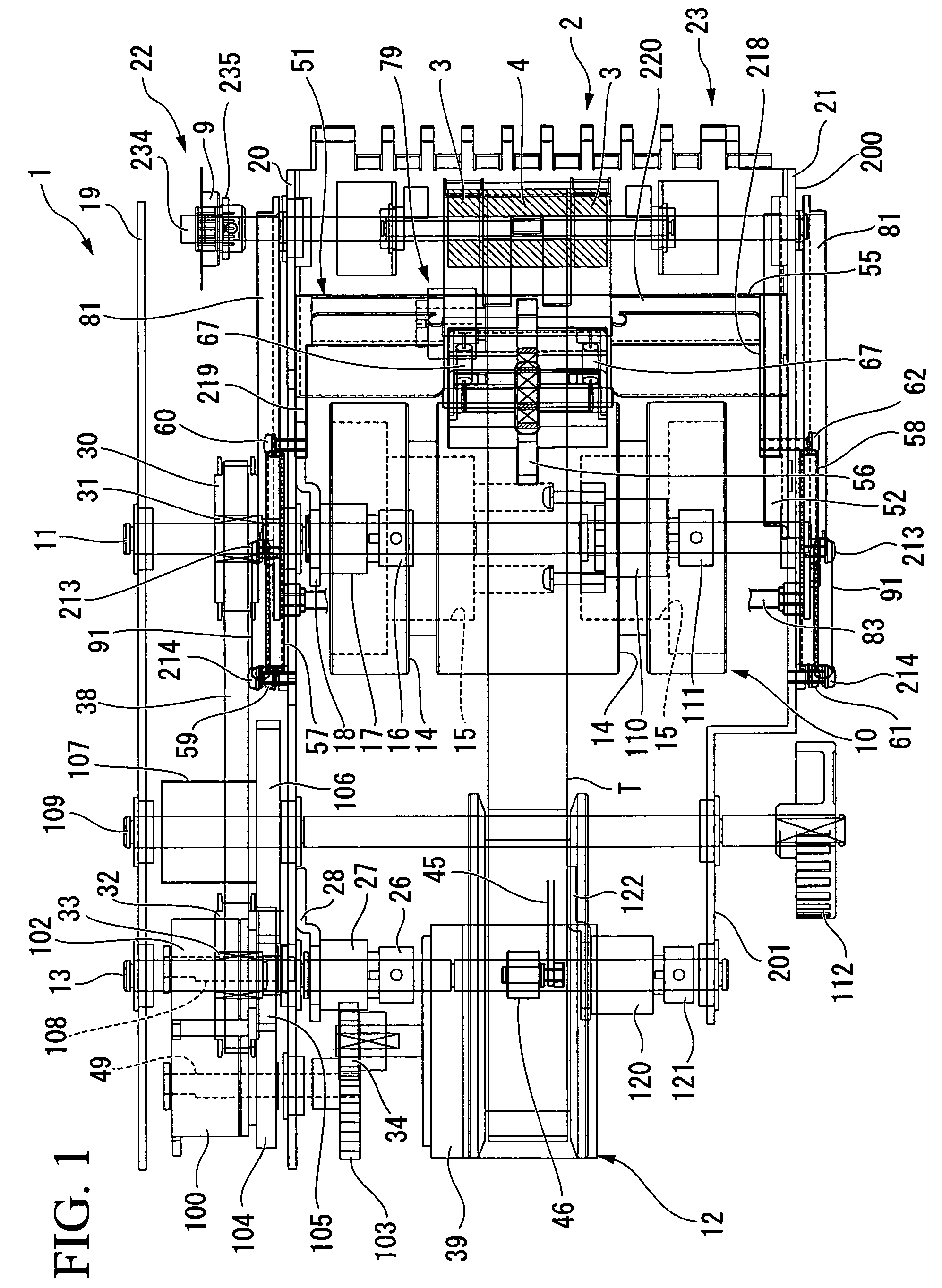
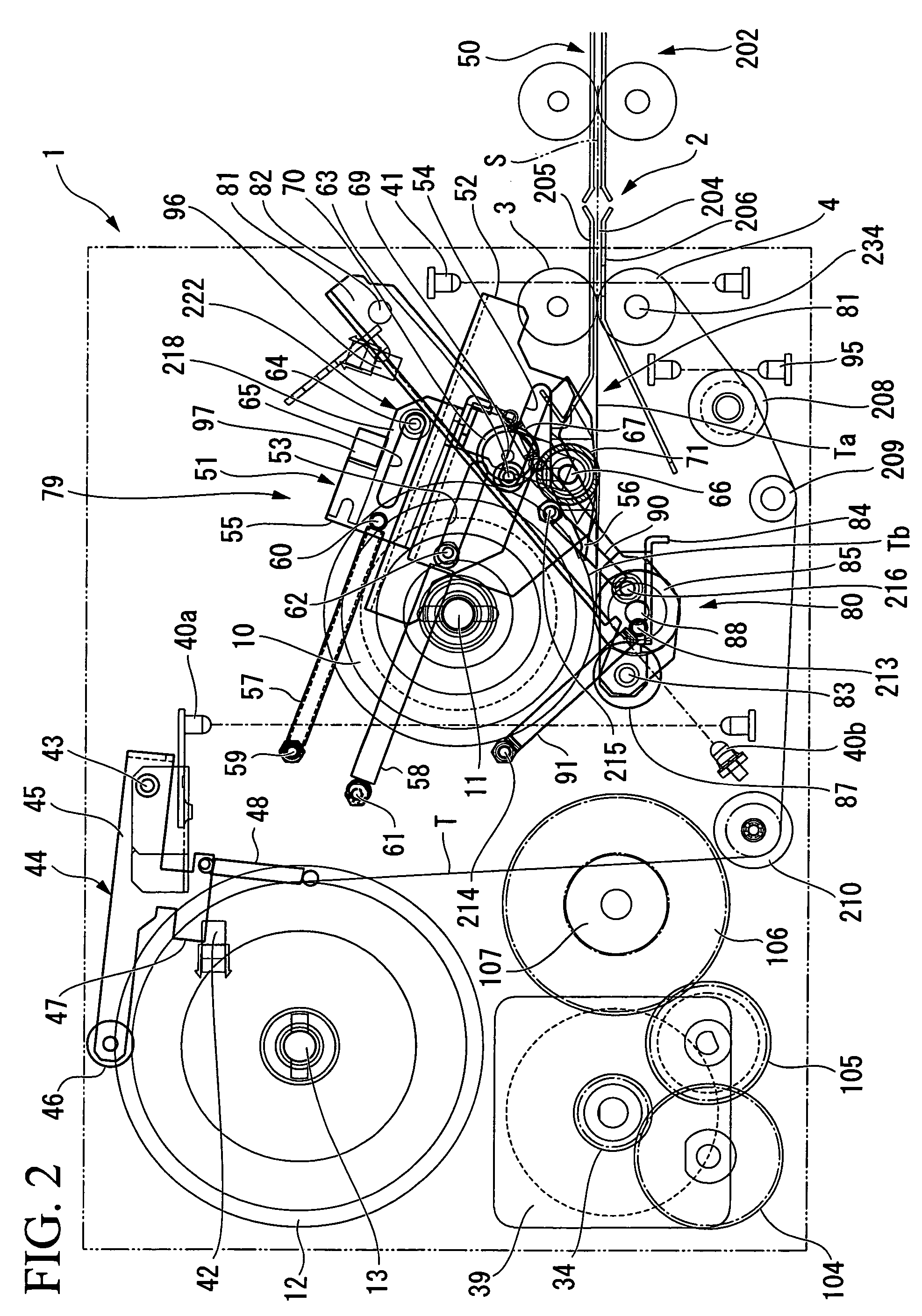
[0043]The paper sheet storage and payout device 1 of this aspect is used in a temporary storage portion and monetary type-specific storage portion of a paper currency receiving / dispensing unit which handles, as paper sheets, paper currency S. That is, the paper sheet storage and payout device 1 replaces a conventional paper sheet storage and payout device which accumulates and stores paper currency in a box-shape space, and pays out one bill at a time from the bottom or from the top. The paper sheet storage and payout device 1 of this aspect can handle international paper currency, which differ in size according to the monetary type, and transports and stores paper currency with the long-edge direction aligned in the transport direction.

[0044]Referring to FIG. 1, the paper sheet storage and payout device 1 is subdivided into a driving system space 22, enclosed b...


PUM

PropertyMeasurementUnit
angleaaaaaaaaaa
angleaaaaaaaaaa
angleaaaaaaaaaa

Abstract

A paper sheet storage and payout device, which, by winding and unwinding tape between a first take-up drum on which the tape is wound from one end, and a second take-up drum on which the tape is wound from the other end, with paper sheets placed thereupon, stores and pays out paper sheets. A separation mechanism is provided on the payout side of the tape from the second take-up drum, and during payout separates the paper sheets from the wrapping peripheral region of the tape wrapped around the second take-up drum. This separation mechanism is provided with a separation member which separates paper sheets from the wrapping peripheral region, and a sliding portion which holds the separation member, and which slides so as to track the amount of tape wrapped around the second take-up drum by bring into contact with the wrapping peripheral region a guide roller.

Description

BACKGROUND OF THE INVENTION[0001]1. Field of the Invention[0002]This invention relates to a paper sheet storage and payout device, employed in paper currency processing equipment and similar, which stores and pays out paper sheets by means of the winding and unwinding of a tape.[0003]Priority is claimed on Japanese Patent Application No. 2005-111922, filed Apr. 8, 2005, the content of which is incorporated herein by reference.[0004]2. Description of Related Art[0005]A conventional paper sheet storage and payout device of this type is described in Japanese Unexamined Patent Application, First Publication, No. 2002-160855. This paper sheet storage and payout device has a first take-up drum which winds the tape from one end, and a second take-up drum which winds the tape, with paper sheets placed thereupon, from the other end. This device, by rotating the second take-up drum in one direction, winds and stores paper sheets together with the tape onto the second take-up drum, and by rota...

Claims


Application Information

Patent Timeline
Patent Type & Authority Patents(United States)
IPC IPC(8): B65H5/22B65H39/14
CPCB65H5/28B65H2301/4191B65H2701/1912G07D11/16G07D2211/00
Inventor OISHI, TAKIEGASHIRA, MASAAKISUWA, MASARU
Owner LAUREL PRECISION MACHINES
Learn More